Chapter 10
Further Issues in Character Animation
Before going on to the issues of lighting, rendering, and editing, there are a few more topics I’ll cover here. In the first part of this chapter, I’ll give you an idea of how you can use constraints to incorporate props smoothly into your character animations. The rest of the chapter is concerned with various ways to represent particular physical effects. For example, with lattices and mesh deformers, you can deform your meshes in ways that would not be easy or even possible using only bones. The softbody system simulates realistic soft object behavior, and with metaballs, you can create interesting effects that are not possible with meshes.
- Interacting with Props
- Lattices and Mesh Deformers
- Softbodies and Metaballs
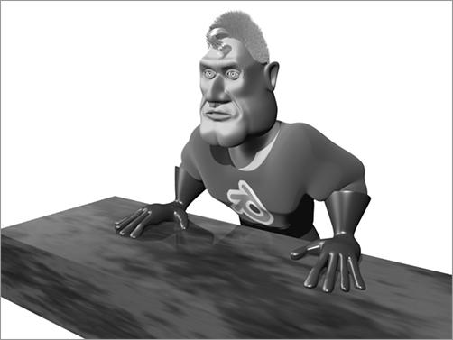
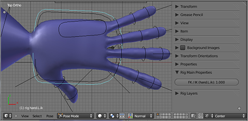
, you want the figure’s hands to stay fixed to the table, in spite of the other motion of the rest of the body. The character should be able to stand and sit or lean forward or to the side, without the hands moving from their position on the surface of the table. You can do this by setting the hands’ FK/IK value to 1 in Rig Main Properties in the Properties Shelf, as shown in . If you want to animate this value, you simply press the I key over the value. Once you have the arms set to IK posing, you pose the hand.IK bones first, and then you can animate the body while keeping the hands fixed, as shown in .
Grabbing and Holding Objects
Many props, however, are more than just obstacles, so they require a different approach. In many cases, the character needs to hold and manipulate the prop. This is not as simple as the case of furniture because in this case you want the prop to behave as an extension of the character itself when being held but to behave as an independent entity when not being held.
With a sword or a stick, for example, you want the prop to be poseable in the same way that the character is poseable if the character is using the weapon to fight. It would be far too complicated and inflexible to key the object entirely independently. Nevertheless, if the character drops or throws the prop, it should no longer depend on the character’s movements.
You can do this by using copy location constraints (and in some cases copy rotation constraints), as you will see in the simple example of Captain Blender picking up and throwing a ball.
Picking Up and Throwing a Ball
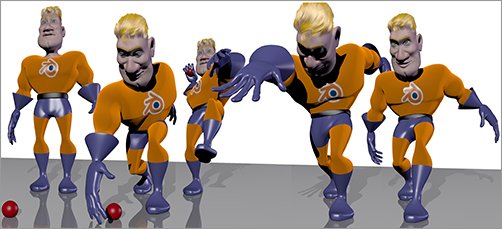
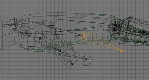
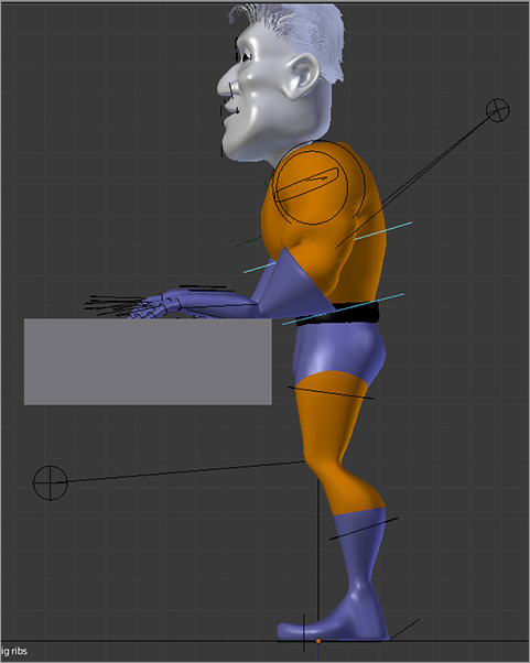
This example focuses on using constraints to enable good prop interaction. I’m not going to go into the various bone poses that compose the action. gives an overview of the full animation.
The animation shows Captain Blender crouching forward, grasping the ball, pulling back for a pitch, and throwing the ball. The main concern in this section is the motion of the ball when Captain Blender is holding it in his hand. Of course, with an object F-Curve, you can control the movement of the ball for every frame in the animation if you want. You could simply key the ball’s position to follow Captain Blender’s hand.
But an object F-Curve is not a good solution. If you do this, you might need a large number of keys to make the ball follow the motion of the hand, even if the motion itself is determined by only a few bone movements. Furthermore, if you edit the throwing action at all, which is very likely with a movement like this, you have to adjust or even rekey many location keys for the ball. Clearly, what you want to do is to have the ball follow the hand’s motion automatically.
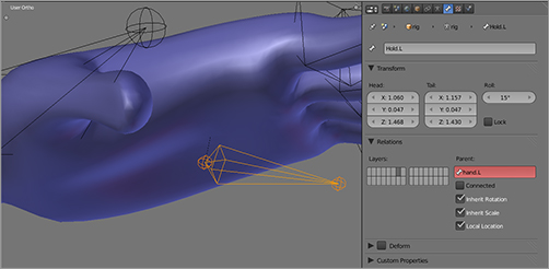
To make this possible, you will create a new bone by extruding and detaching a new bone from hand.L/R, called Hold.L/R, as shown in . Extrude with the E key (the edits should all still be mirrored, so you can do this on either hand) and then detach the bone by pressing Alt+P and selecting Disconnect Bone. This bone is located in the middle of the space just below the palm of the hand, in approximately the spot where you would like a held object to be, as you can see in . It is not connected to any other bone, but, as mentioned, it is parented to the hand bone.
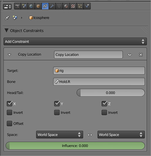
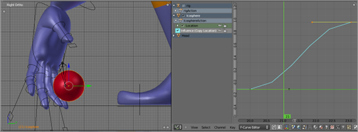
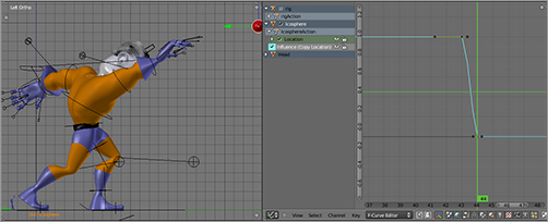
After you create and place the ball (a subsurfed icosphere), set up a copy location constraint on the ball, as shown in . In the OB field, type the armature’s name, in this case simply rig. When you enter an armature’s name in this field, a second field appears for the bone name. Name it Hold.R bone here. Use the slider to set the influence to 0.
The influence slider determines to what extent the ball’s location is determined by the constraint. If the slider is set to 1, the ball is fixed to the hold.R bone’s location. If the slider is set to 0, the ball will return to its original position or the position that it is keyed to as an object and be completely independent of the bone or armature’s movement. Intuitively, a value of .5 places the ball halfway between its own original (or keyed) location and the location of the hold.R bone.
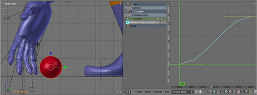
Most importantly, you can key the influence of the constraint to an F-Curve by pressing the I key over the influence slider. In this way, you can animate smooth transitions in the influence of the constraint. You begin by keying the constraint influence to 0 and keying the ball’s location to the place you want it to be at the beginning of the animation.
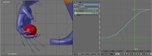
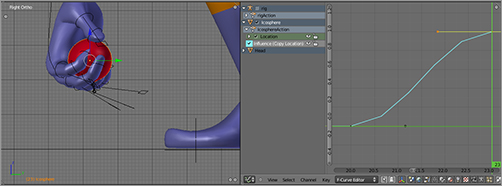
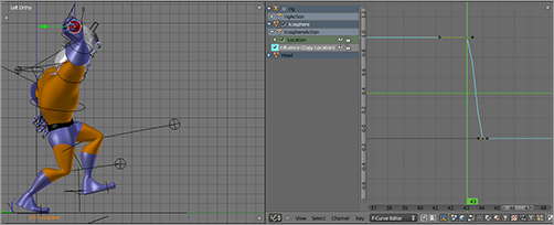
You can see constraint influence F-Curves by looking in the Graph Editor. follows the copy location constraint’s influence curve from 0 to 1 as Captain Blender picks up the ball. follows the more sudden release of the ball when he throws it. Note that the Graph Editor is scaled slightly differently in , so it is important to pay attention to the values themselves.
The ball’s location needs to be keyed so that when the constraint influence is turned off, it will spring to the appropriate location. You need to take the actual location F-Curves of the ball into account, even when the constraint is active.
For example, if you keyed the ball’s location to the ground in frame 1 and made no more location keys until the point after the ball is thrown, you would see the ball begin to float toward that destination even before the character picked it up. For this reason, you will need at least one duplicate key of the ground position, located after the ball has been picked up, to keep the F-Curve flat up until that point.
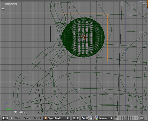
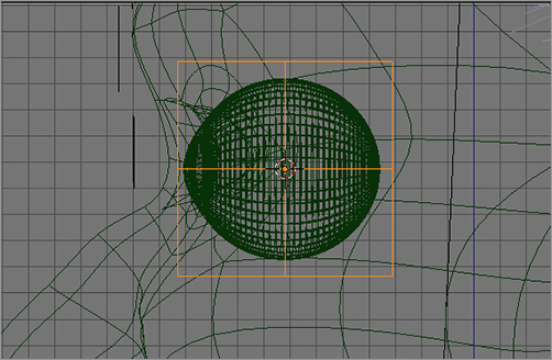
. Resize the object to fit around the eyeball, as shown in . Make sure you do not do this resize in Edit mode; otherwise, your eyeball will shrink as soon as you apply the lattice.
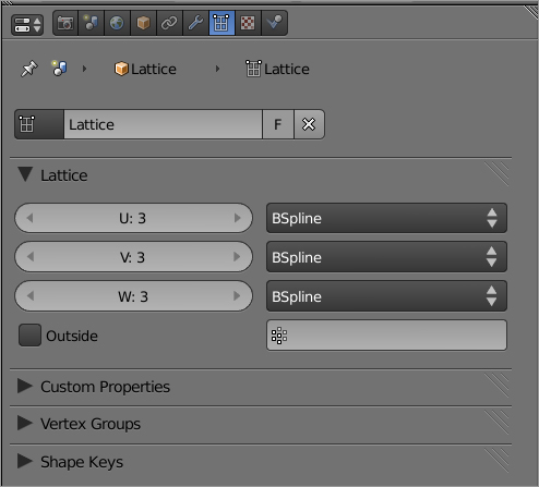
2. In the lattice properties panel (see ), set the lattice resolution to 3 along the dimensions U, V, and W, resulting in the lattice shown in .
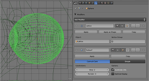
3. Select the left eyeball object, and add a Lattice modifier on the Modifiers tab. In the Object field, enter the name of the lattice, Lattice, as shown in . Take care to select the correct eyeball, which might require reorienting the view slightly to double-check.
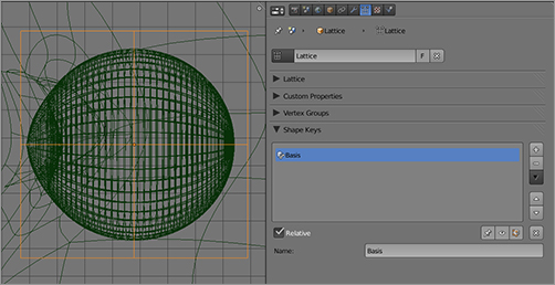
4. With the lattice selected, find the Shape Keys panel in the Lattice Properties window, as shown in , and add a Basis shape key by clicking the plus icon just as you did with meshes in Chapter 5.
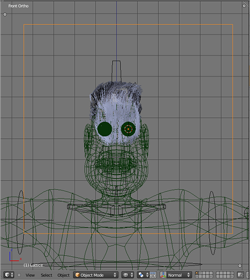
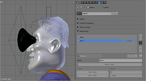
5. Still in Object mode, add another shape key by clicking the plus icon. With this shape key (Key 1) active, enter Edit mode, and edit the shape of the lattice, as shown in . Notice that when you move lattice vertices, the mesh is also deformed in a corresponding way. Edit the lattice so that the eye bugs out of its socket.
That’s all there is to it. You can use lattice shape keys in all the same ways that you use mesh shape keys, including setting up drivers. Be sure to parent the Lattice object to the eyeball using ordinary object parenting so that the lattice moves with the eyeball if you animate the character. After you’ve finished this, you’re ready to incorporate this effect into a full facial animation, as shown in . Remember what I said before about exaggeration?
Mesh Deform Modifier
A Mesh Deform modifier behaves similarly to a lattice but is more flexible in that its initial shape is based on a mesh that you model yourself. Like a lattice, it can deform a mesh using shape keys or in real time in Edit mode. However, unlike lattices, the mesh deformer can also be rigged directly with an armature and weight painted, just like any other mesh. (It is possible to control a lattice with an armature, but you must do this in a somewhat roundabout way, using hooks. This is touched on briefly in Chapter 15.)
In this section, you’ll see an example of an alternate way of rigging Captain Blender’s legs using a Mesh Deform modifier instead of using an armature directly. In this example, the Armature modifier has been deleted from the Captain Blender body mesh, so the rig does not have any direct influence on the character mesh.
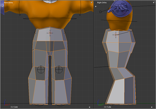
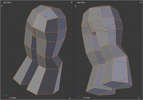
To deform the legs using a Mesh Deform modifier, you must first model the deform mesh, as shown in . This is an ordinary Mesh object, modeled from the default cube. It must fully cover the area that you intend to be deformed by it. Parts of the character mesh that are not fully contained in this mesh will not be deformed by it.
Be careful if your character mesh is subsurfaced, as in this example, because this may cause the mesh to appear smaller than it really is. The unsubsurfaced “true” edit cage of the character model must be completely enclosed by the deform mesh. Furthermore, the deform mesh must be a fully closed simple manifold mesh. There can be no missing or unconnected faces, and the mesh should have a well-defined inside and outside. In , you can see that the leg deformer mesh used in this example conforms to this requirement.
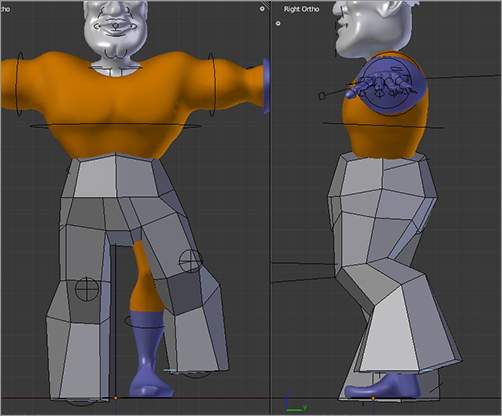
Obviously, the deform mesh is no different from any other mesh, so you can rig it to the armature in the same way you would rig any other mesh, using Ctrl+P and selecting an Armature deform with automatic weights. Having done this, you can pose the deformation mesh with the armature as in . Note that the Captain Blender character mesh is not rigged to the armature.
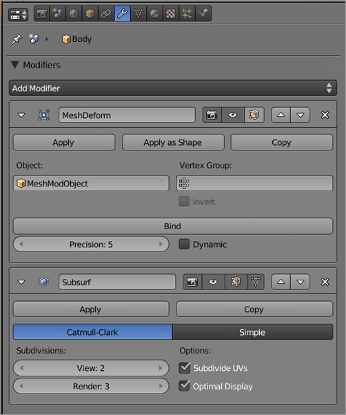
Now you can add a Mesh Deform modifier to the Captain Blender body Mesh object, as shown in . As with the Armature modifier, the Mesh Deform modifier should be above the subsurf modifier so that the deformed mesh is subsurfed. You must enter the name of the deform Mesh object, in this case MeshModObject, in the Object field.
Before the Mesh Deform modifier will work, you need to click the Bind button to bind the character mesh to the deform mesh. When you do this, any change to the deform mesh will deform the character mesh. If you want to edit the deform mesh after this point without changing the character mesh, you must unbind the modifier and then rebind it again when you are ready to use it again. Be aware that binding the mesh can take time. If you have a complex deform mesh, binding can slow things down considerably for a while. Don’t worry, though, your computer (probably) hasn’t crashed.
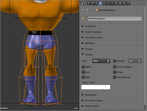
For visualization purposes, I have set the deform modifier to display with the Wire display type, as shown in . Of course, in practical rigging situations, you would probably make the deform mesh invisible to animators, but wireframe view is a good way to see what’s going on with the deform and character meshes.
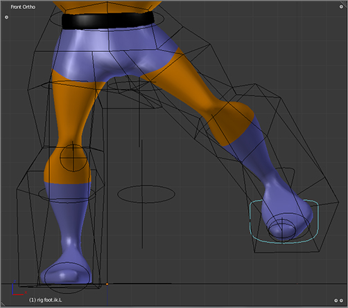
Now, when you pose the armature, you get the results shown in . Note what’s happening here. The armature is influencing the deform mesh, and the deform mesh is deforming the character’s leg. This results in a considerably different pattern of influence on the surface of the character mesh and can yield smoother deformations than direct armature influence.
Certain character shapes can benefit greatly from this kind of deformation. For example, a round character with rolls of fat or some other complex aspect to its shape might not be handled well by the automatic bone weighting algorithm and might be much easier to rig using a simple mesh deformer.
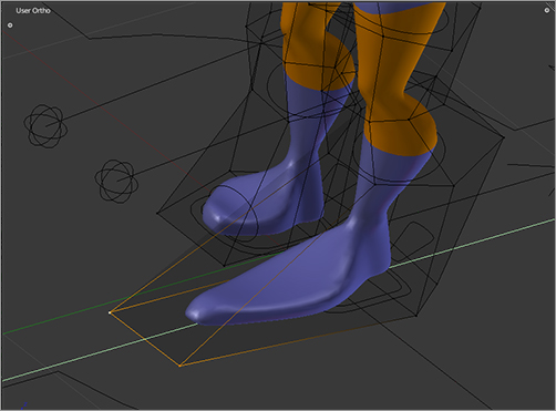
As you can see in , a bound deform mesh deforms the character mesh when it is edited in Edit mode. You can use this for shape key animation in a similar way to the lattice example that you saw previously.
.
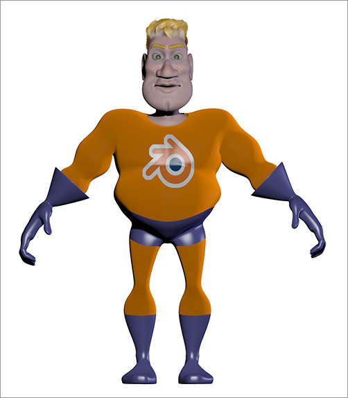
I’m not going to go into any depth on the modeling of Captain Blender’s new physique, because it was simply a matter of pushing a few verts around and adding a few edge loops, as you can see in . (When you make this modification to the model, be sure to use Save As so as not to ruin to your original file.) What you’re concerned with is how to apply a softbody simulator to Captain Blender’s new belly to give it some real jiggle as he strives to get back into shape with a grueling regimen of jumping in place.
To apply softbody behavior to Captain Blender’s belly, follow these steps:
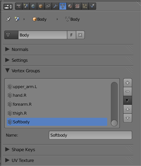
1. Because you want part of the mesh to be soft and part of the mesh to retain its form completely, you need to use a vertex group. With the Captain Blender mesh selected, tab into Edit mode, and on the Links and Materials tab, under Vertex Groups, click New. Name the new vertex group Softbody, as shown in . Select all vertices in the mesh, and assign them all to the vertex group, making sure that the weight is set to 1.
You don’t really want all the weights set to 1. In fact, for the portion of the mesh that you want soft, namely, the belly, you want the weights set to around 0.25.
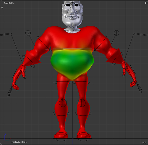
2. Enter Weight Paint mode, and select the Softbody vertex group from the Vertex Groups drop-down menu. Using the Weight Paint tool with Weight set to 0.25 and Opacity set to 0.5, paint the belly as shown in . It will work best to use X-Axis Mirror. Around the edges of the 0.25 area, paint at 0.5 weight. The whole mesh should be red in Weight Paint mode, except for the belly, which should be green. The area just below the sternum should be yellow. When you finish weight painting, switch back into Object mode.
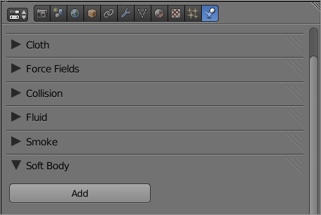
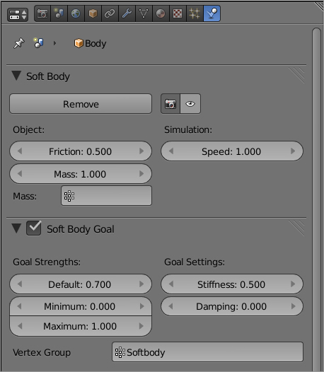
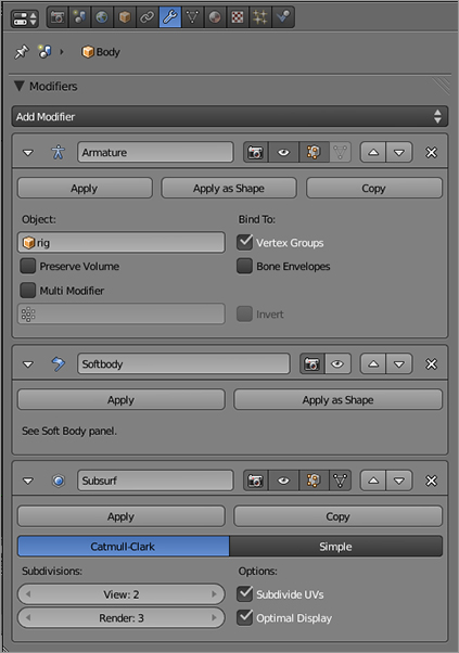
3. In the Physics Properties area, click Add in the Soft Body panel, as shown in . Set the settings for Soft Body and Soft Body Goal as shown in .
These are general parameters for the soft body simulator and parameters to control how much the simulation adheres to the “goal.” In this case, the goal will be your Softbody vertex group, so enter that into the Vertex Group field as shown.
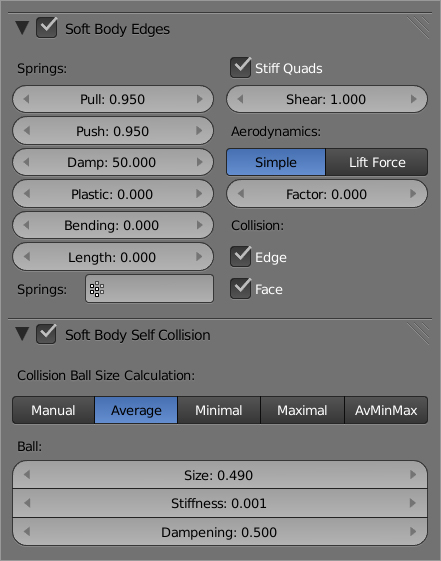
4. Set the values for for Soft Body Edges and Soft Body Self Collision as shown in . These determine how flexible or bouncy the edges of the mesh are during the simulation and whether and how accurately the mesh collides with itself.
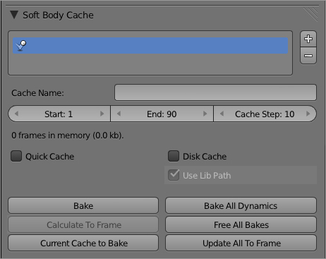
5. shows the settings for Soft Body Cache. These are parameters that control caching and baking of soft body simulations.
For information on what the various individual fields actually do, hover your mouse over the field and read the tool tip that pops up. However, even with this information, finding the correct settings for a specific use often involves some trial and error, and you should expect to do a lot of experimenting before you have an innate sense of how these parameters affect the outcome. Unfortunately, it’s beyond the scope of this book to go into all of these parameters in more detail.
6. Now you have the softbody simulator set up. Check on your modifier stack. You’ll see that a modifier has appeared called Softbody. However, you want the Softbody modifier to be sensitive to the movement of the character’s body. To have that information, it must have access to the movements created by the Armature modifier. If you think back to Chapter 2, recall that the ordering of mesh modifiers is closely bound up with what kind of information is available to each one. In this case, the Softbody does not react to Armature motion as is. You need to bump the Softbody modifier down a notch using the down arrow button on the modifier itself so that the Softbody modifier follows the Armature modifier (see ).
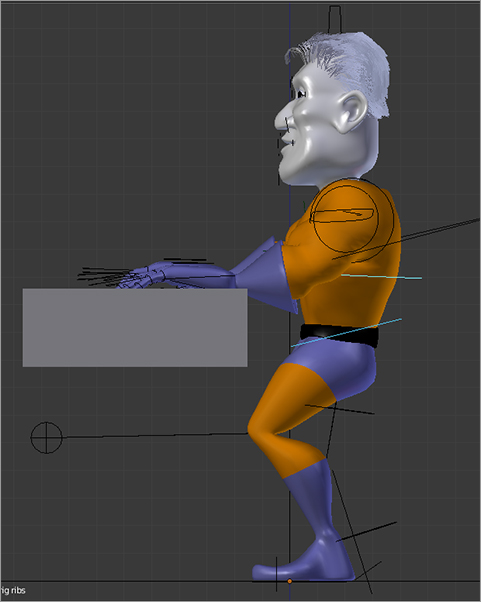
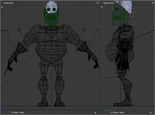
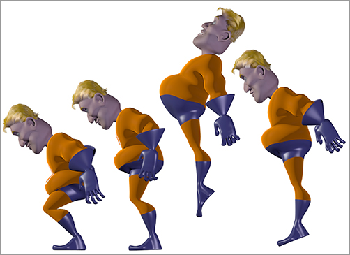
After you do this, you’re good to go. Preview your animation to see the effect of the Softbody simulator. shows a side view wireframe representation of several frames from this simulation.
Metaballs
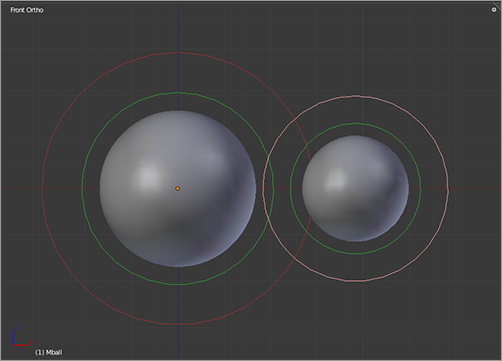
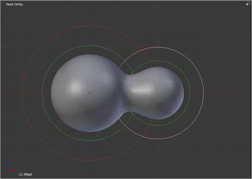
Metaballs are spherical mathematical constructs that merge or cling together when placed within a set proximity of each other, as shown in . They are a very limited tool for modeling, but their liquid-like properties are very difficult to mimic in any other way.
Perhaps the best-known Hollywood examples of what metaballs can be used for are the liquid metal character in Terminator 2 and the animated green goop from Flubber. Metaballs are the basis for the Meta Object type in Blender, and the various meta-objects are all essentially built from the basic metaball.
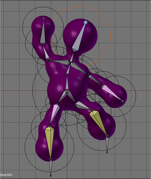
Although metaballs cannot take an Armature modifier, you can use bone parenting to control the movements of metaballs with an armature if the metaball model is built of separate metaball objects that can be parented independently, as shown in .
To parent a metaball to a bone, make sure that the armature is in Pose mode, select the metaball object (Blender reverts to Object mode automatically), select the armature again (Blender reverts to Pose mode), and, with the desired bone selected, press Ctrl+P. Select the option to parent to a bone.
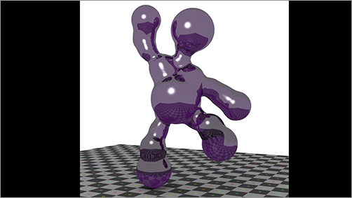
In this way, you can create a poseable character with metaballs that also retains the liquid qualities special to metaballs, as you can see in .
In this chapter, I tried to give you a hint of some of the possibilities for animation in Blender. Unfortunately, there are many useful and interesting tools and tricks that I do not have space to cover. Using dupliverts, duplipaths, and dupligroups; using curve deform; and using modifiers such as array, build, and wave—these are all topics that warrant extensive discussion but are outside the scope of this book. In Chapter 18, I point out where to find out more about these and other useful functions.
Indeed, there is really no end to the possibilities for both modeling and animation by using Blender’s various tools. I hope that what you have read so far has begun to whet your appetite. It is far from the end of the story. In Chapter 11, you’ll look at the basics of how to light and render your scenes to create good-looking, fully realized images. You’ll also see how to use the Blender Sequence Editor to combine sequences of rendered images to create completed animations.