Chapter 11
Lighting, Rendering, and Editing Your Animation
At this point, you’ve learned the basics of creating and animating characters in Blender. However, before you can see your animations the way you envision them, I need to go over some fundamentals of presenting and outputting your work. In this chapter, I’ll give you a brief overview of Blender’s lamps and lighting system and then explain how to light your scenes and characters. I’ll also describe the process of rendering and talk about your options there. Finally, I’ll give you a bit more information about the Sequence Editor and tell you how to output finished animated sequences in the format you want.
Lighting, rendering, and editing are all topics that deserve a great deal more attention than what I’ll give you here. This chapter will scratch the surface of what there is to know about these aspects of CG animation and of Blender’s capabilities in particular. See Chapter 18 for references and further information on these topics.
- Lighting Basics
- Rendering Your Animation
- Editing in the Sequence Editor
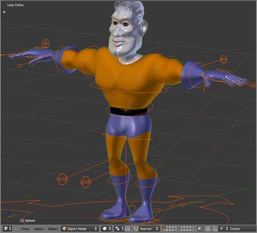
, although the object appears “shaded,” this shading is specific to the Blender 3D viewport and does not reflect the lighting setup you will use to render (you can adjust the viewport shading setup in the user preferences, specifically, in the Solid OpenGL Lights area in the System panel). This is the default view mode, and on most ordinary computers it is much faster to work with than any other view (except, of course, wireframe).
To get a better sense of the shading based on the actual lighting of the scene, you can activate GLSL viewport rendering by selecting GLSL in the drop-down menu under Shading in the Display panel of the 3D viewport Properties Shelf. GLSL viewport rendering enables high-quality real-time rendering of textured objects if you choose Textured Viewport Shading from the drop-down menu in the 3D viewport header, as shown in .
Solid view
GLSL textured view mode
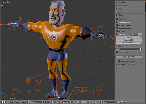
This view will update in real time as you move the lamp, but it is computationally expensive, so many processors will experience a significant lag. Some older video cards do not support GLSL, so this option may not be available.
These various tools can be useful in placing lights, but I find that for assessing lighting, nothing beats a proper render.
Cheats
A cheat in film lighting terms is an unnatural or unlikely use of light to give a desired effect. Because a film audience views a scene with fixed borders and from limited angles, it is possible to take many liberties even with real lights (adding light sources that would not exist in nature, moving light sources from their “true” positions, and so on).
Cheats are the norm in traditional lighting and even more so in CG lighting, in which moving lights costs nothing and adding lights costs only additional render time. Nevertheless, it is a good idea to have a sense of when you are using cheats and to consider the ultimate effect of your lighting on the viewer. Always have an idea of what the actual lighting situation in the 3D scene should be and where the viewer should perceive the light as coming from. Because they are by definition unnatural, cheats should never be obvious to the viewer.
Lamps
Lights are represented by the object type Lamp, which has the following subtypes:
- Point
- Spot
- Hemi
- Area
- Sun
The Lamp properties, shown in , are accessible in the Properties window when a Lamp object is selected. The figure shows a typical example of the buttons and parameter values for a spotlight.
Lamp properties
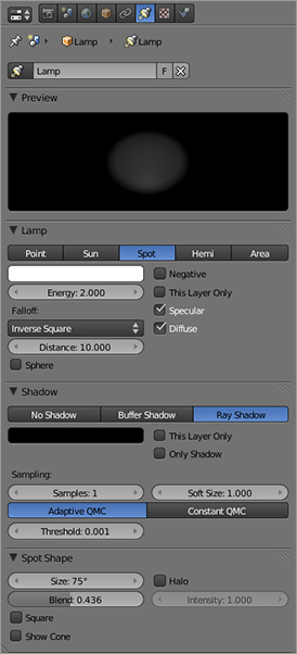
You select the lamp type from the buttons along the top of the Lamp panel. Below that, you access parameters such as the lamp’s Distance, Energy, and RGB color values. In the Shadow panel, you access the parameters that govern the way the lamp casts shadows. In the case of spotlights, you can adjust the size and shape of the spotlight cone in the Spot Shape panel.
Control over shadow properties is one of the areas in which CG lighting differs most drastically from traditional cinematographic lighting. Unlike reality, you can switch the shadows cast by a lamp on and off completely independently of the lamp itself. Furthermore, you have a choice between several different methods of calculating the shadows. You can use either buffer shadows, which are relatively quick to calculate and approximate, or ray shadows, which more accurately reflect the shapes and properties of the objects casting the shadows.
The graphic representation of the light in the 3D viewport tells you what shadow options are active on the light. In , you can see the three options active for a spotlight, in order of appearance: no shadow, buffer shadow, and ray shadow.
Each of the different lamp types has specific properties and options that can be associated with it, and each has its own uses in practice. In this section, you’ll look briefly at the different lamps and their effects.
No shadow, buffer shadow, and ray shadow options for lights
Point Lamp
The default lamp is a Point lamp (also known as an omnidirectional light) that can cast ray shadows or have shadows completely disabled but does not have an option for buffered shadows. The Point lamp offers no control over the direction and throw of the light beam. shows an example of the light provided by the default lamp. (This render used the ray shadow option for cast shadows.)
Lighting by a single lamp
Although something approximately like omnidirectional lights is common for household lamps and streetlights, there are not a lot of omnidirectional lights on movie sets and theatrical stages. But there are a lot of spotlights. The reason is simple: lighting requires control over where the light goes. Spotlights give this control; omnidirectional lamps don’t.
In the present example, with a single lamp illuminating a single subject, the difference is negligible. However, when you have more than one subject and are concerned with lighting various parts of a scene convincingly with shadows, highlighting, and fill lights, you very quickly run into situations in which you cannot do without the control you get with spotlights. Furthermore, because the default lamp casts light from a single point, it is inappropriate to use on its own for ambient light and is not especially suited for soft fill light. So, in spite of its apparent generality, the default lamp is actually quite limited in its practical applicability. It is useful as a prop light, for example when you have a lamp in your scene that needs to cast omnidirectional shadows. But for actual lighting, I rarely use the default lamp.
Spot Lamp
The spotlight is the most frequently used type of light in most lighting situations. The light has the same qualities as that of the default lamp, but you can control the beam. The direction, distance, width, and sharpness of the beam are all parameters you can set in the lamp buttons area.
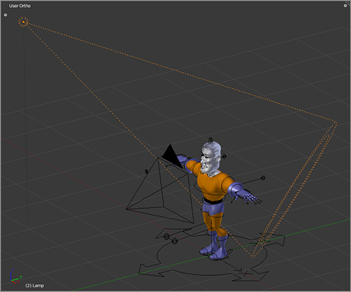
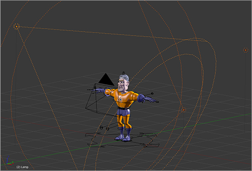
shows the spotlight setup for the renders that you’ll see in upcoming figures. Notice that the throw of the spotlight is clearly represented in the 3D viewport.
Unlike the default lamp, spot lamps have three options for shadows. These options have different applications, and there are some potential quirks to be aware of.
Spotlight setup in the 3D viewport
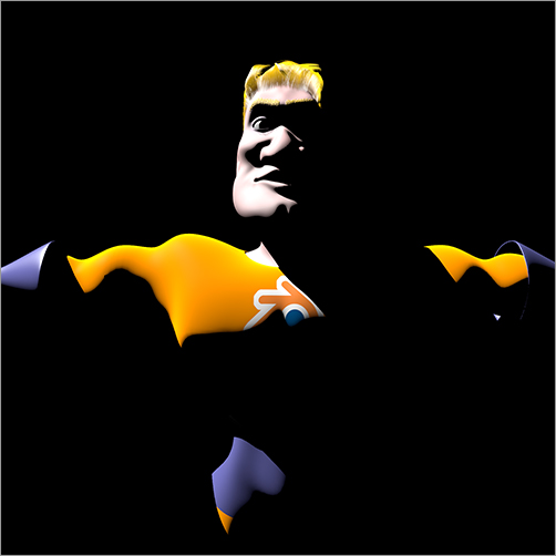
No Shadow
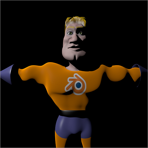
Using lamps with the shadow turned off is a classic CG cheat. In , you see a render with shadow off. Note that the render still has places that are in shadow. They are simply the places where the light does not reach. In CG (although not in the physical world), the shading of objects is a completely separate phenomenon from cast shadows. Shadows thrown from one object onto another are calculated separately from the increase in energy on surfaces that are facing the light source.
Spotlight with no shadows
Being able to turn off cast shadows can be very convenient; unwanted shadows are the bane of complex lighting setups in traditional lighting. However, there are issues to be aware of. Like any cheat, it is noticeable if used in an obvious way.
If your character is walking through the desert under a hot sun, turning off cast shadows is unnatural and distracting. In general, the light source that your audience perceives as the main light source (which might or might not truly be the main light source) should appear to cast shadows. Nonshadow lights are very good for fill lights, however, because they eliminate the real-world problem of double shadows that occurs when using fill lights that cast shadows.
When cast shadows are turned off, direct light affects surfaces naturally, but the shadows that shapes cast onto other surfaces are not calculated. In effect, objects and parts of objects become transparent in relation to each other. In some cases, the result can be problematic, causing the appearance of glowing nostrils or hair that appears to be lit from within.
Buffer Shadow
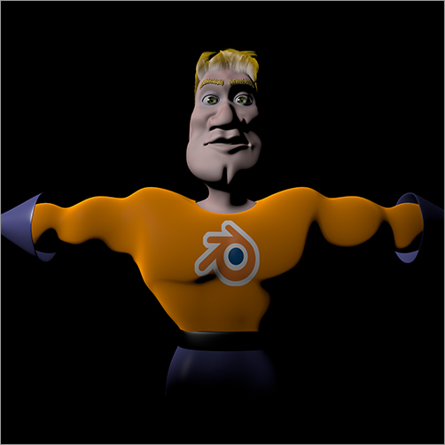
Buffer shadows work by making a grayscale render of the occluding objects from the light’s point of view and then mapping that image onto surfaces behind the object. The shadow cast by the character’s head onto his left shoulder in is a buffer shadow. Contrast this with the unnatural highlight in the previous figure, in which no shadows are cast.
Spotlight with buffer shadows
Buffer shadows can be relatively quick to compute and are often very efficient to use. However, in certain cases the limitations of buffer shadows become apparent. Buffer shadows are cast at a fixed resolution, which must be set in advance. If the resolution is insufficient, the shadow can become pixelated. Only the Deep option for buffer shadows supports transparency, at the expense of greater computing time.
Ray Shadow
Ray shadows are calculated by tracing the light beams emitted from the lamp, in a way most closely approximating the way that actual shadows fall in nature. This yields the most accurate shadows; the qualities of the shadows are entirely dependent on the lighting conditions.
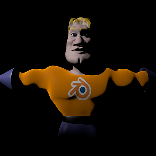
The shadows in were generated using ray shadows. Because there is only one light source, they are dark and sharply defined, as would be the case in nature. They convey somewhat more definition of the shape of the character and handle the transparency of the eyes better than the Deep buffer shadows in the previous example. However, the cost is considerably longer render time with more complex scenes, so buffer shadows are often the better alternative.
Spotlight with ray shadows
Hemi Lights
Hemi lights provide a very diffuse light source, meaning that the rays of light are scattered and moving in many different directions. This is typical of light in many real-world conditions, in which much of the light you see is reflected. In this respect, hemi lights are both more “naturalistic” than spots and much less naturalistic because no lamp exists in nature that is capable of producing the kind of illumination that hemi lights produce.
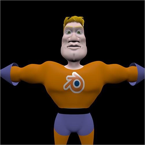
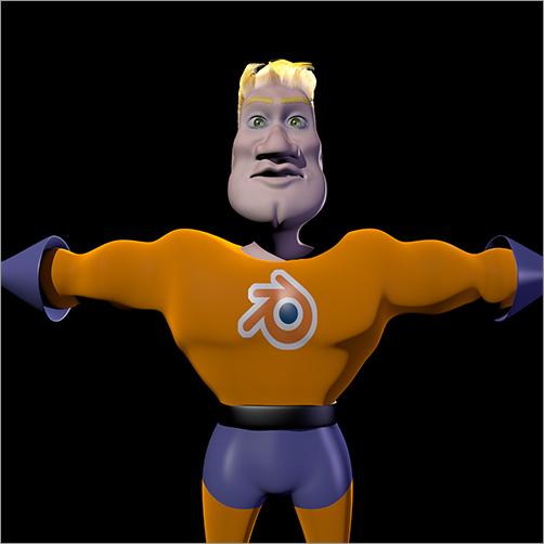
In , you can see the figure lit by a single hemi lamp, positioned in the same place as the spot from the previous renders. Note that although there is a tendency for the highlights to be on the right side of the figure and the shadows to be on the left side, there are actually no completely unlit areas anywhere on the figure.
Hemis are sometimes useful for nondescript, utilitarian lighting purposes. Putting a Hemi into a file with a model results in inoffensive and fully visible renders of your model, and it is a good choice for a default light for a model when the model itself is the emphasis of the render. It is not a very good choice for serious lighting, however, because it will result in a flat and lifeless appearance, as in the render in .
Hemi lamp
The hemi light is not generally very good for showcasing objects or for lighting complex scenes. When working with animation, however, in which you try to reduce your render times per frame as much as possible, a hemi light can be useful as a fast, though not very accurate, outdoor fill light. When kept at low intensities and paired with a good key light for the sun, it can help you produce passable renders faster than with other methods. A hemi placed in the 3D space illuminates the whole rendered area. It does not matter where the hemi lamp actually is. The hemi is sensitive only to the angle at which it is placed. All the subjects of the scene will be lit from exactly the same angle, regardless of their position with respect to the hemi.
Sun Lamp
The sun lamp has the same uniform directional properties as the hemi lamp. Like the hemi, it will result in a uniform angle of lighting for all subjects in a scene, regardless of the lamp’s position in the 3D space. All that matters is the angle of the lamp. This resembles the sun in that sunlight, because of the distance of its origin, behaves as a uniformly directed light source. The differences between sun and hemi lamps are that the sun lights only from a single direction, and that you can enable ray shadows with a sun lamp. As you can see in , the lighting is much starker than that of the hemi.
Sun lamp
In spite of its name, the sun lamp doesn’t really produce what you typically think of as sunshine. You will need more than a single sun lamp to light a sunny outdoor scene convincingly. The main thing the sun lamp provides is a way to light multiple objects from a uniform direction, for example casting parallel shadows with only one light source.
Area Lamp
Area lamps represent light that emanates from a large area and can be used in certain circumstances to represent the kind of light that comes from the sun, the moon, or an explosion. These lights are also often used in architectural rendering to show light from windows or banks of fluorescent lights and in product shots or any situation in which a real-life photographer or cinematographer would use diffusers.
As you can see in , an area light produces a broad bath of light and can be useful to illuminate somebody peering into a fridge or being abducted by aliens, but it is unlikely to become your first-choice lamp for lighting characters in most situations.
Area light
Lighting Setups
In most cases, you should use more than one lamp for lighting subjects. With more complex scenes, it is almost a necessity. For the simplest lighting possible, a hemi lamp is tough to beat, but it will not result in the most attractive render. Another option is to use ambient occlusion, as you’ll see later in this section.
Three-Point Lighting
Three-point lighting involves using three lamps, typically Spots, with the main illumination provided by the key light, shadows softened by a low-energy fill light, and highlights provided around the shaded portions of the form by backlighting, as shown in .
Three-point lighting setup
Any introductory textbook on lighting for film, photography, or CG will inevitably cover three-point lighting. It is such a ubiquitous and widely recognized approach to lighting that it has become almost a cliché. This, combined with the fact that it almost never occurs in nature and has fallen out of favor with filmmakers working in naturalistic styles, has led to something of a backlash against it among some CG practitioners.
Three-point lighting isn’t naturalistic. But then, neither are bugging eyes, slow-motion bullets, or stretchy human heads. They are all cases of artistic license taken with realism to achieve a visual effect. As such, three-point lighting can have very effective uses.
Three-point lighting was developed as a means to use light to highlight and define shape, which was a basic goal in early cinema and remains a basic goal in most 3D animation. It should be regarded as an important tool, but you should also keep in mind that using stark three-point lighting can give a “studio portraiture” look to your work, so it should be used judiciously.
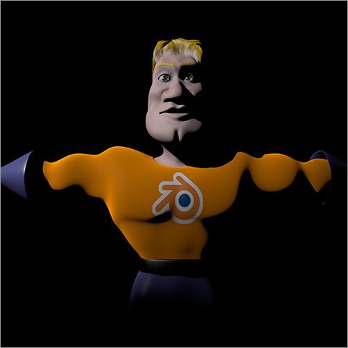
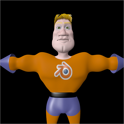
The render shown in uses the three-point lighting setup from the previous figure. In , you can see the effect of each light. In the first render, only the key light is on. This mostly illuminates the subject but leaves the far side of the subject completely in the dark and undefined.
A render with three-point lighting
The second image shows the effect of only the low-energy fill light to the character’s left side. This light serves to reduce the intensity of the shadows and brings the rest of the face into view. Note that even with two spots, the contrast is considerably starker than with a single hemi lamp, as you saw previously. Also, note that the fill light is set not to cast shadows. You don’t want double shadows.
Breaking down the three-point setup: key light, fill light, and backlight
The third render shows the backlight only, which helps bring out the definition of areas that are in relative shadow and adds a dramatic aspect to the scene that is lacking with only the key and fill light.
Incidentally, showing you each light individually is an important thing to be able to do and involves a very handy but not too obvious feature. With complex lighting setups, you often want to see the exact effect of each light in isolation or of some subset of lights in isolation. To do this, you use the lighting Specials menu that you access with the W key in the 3D viewport in Object mode.
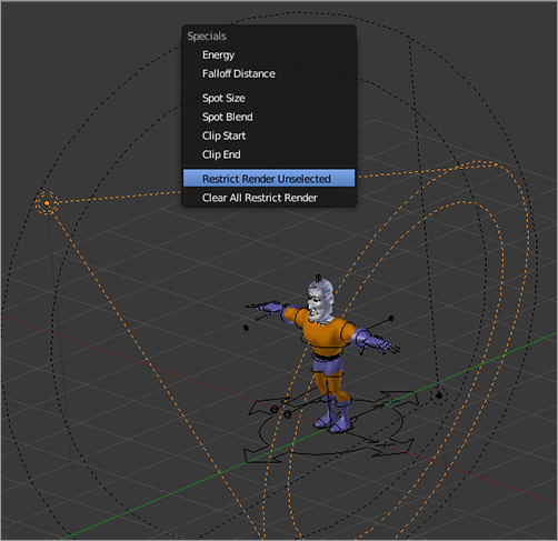
When you bring up the Specials menu, you will be presented with at least two options (more, if you happen to have a light selected): Restrict Render Unselected and Clear All Restrict Render. Choosing Restrict Render Unselected as shown in will suppress the effect of all lights that are not selected at the time. In this case, the rendered scene will be illuminated only by the key light. Choosing the Clear All Restrict Render option will set the scene to be illuminated normally by all active lights.
The Restrict Render Unselected option
Using Layers and Light Groups
Cheating lights is a very important part of creating good CG scenes, and for this reason there are a variety of ways to do it. Two of the most important are layers and light groups. On the Lamp properties panel for each light there is a This Layer Only check box. If this is selected, the light will only illuminate objects that it shares a layer with.
For even more control, you can assign a light group to individual materials. In the Material Properties window, in the Options panel, there is a field labeled Light Group. First, group the lights in the ordinary way that you want to affect that material. When you enter the group name in the Light Group field for that material, only the lights in that group will have an effect on that material.
Ambient Occlusion
Although it does not directly involve lights, ambient occlusion (AO) is worth mentioning in a discussion of lighting. AO is an approach to lighting or shading a scene in which illumination is calculated entirely based upon the geometry of the scene. It makes the assumption that the scene is lit with perfectly diffuse (randomly scattered) light and that the amount of occlusion (darkness) of a surface can be estimated based upon the surface’s proximity to other surfaces.
If you look around the room you’re in now, you will probably notice that wide-open areas such as walls are more brightly lit than the corners of the room and that the nooks and crannies between objects, such as the spaces between books on a bookshelf, are darker than other places. This is likely to be true for almost any ordinary lighting setup, and for this reason, it is possible to simulate without regard to the lights in a scene.
AO can be activated in the World Properties window, by selecting the box on the Ambient Occlusion tab. shows three cases that illustrate the effect of AO. The first image shows the three-point light setup from the previous section only, with no AO effect. Because of the backlighting, the shadow from the key light is very faint. In the second image, AO is used with the Multiply option to darken some surfaces based on their proximity to other geometry. Notice that the edges of the feet are shaded slightly where they meet the ground, resulting in a more anchored appearance. This is a main benefit of AO. In the third image, additive AO is used on its own to illuminate the scene, with all three lights disabled. This produces a perfectly diffuse illumination with no highlights and with shading based entirely on the geometry of the scene.
AO on its own can provide a very appealing source of illumination, particularly for displaying models with an emphasis on their shape. The main downside of AO is that it can add considerable render time.
Three-point lighting without ambient occlusion, three-point lighting with ambient occlusion (multiplicative), and ambient occlusion only (additive)
.
Render properties window
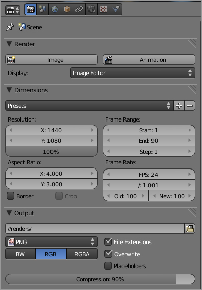
The Render panel simply contains the buttons for rendering a still image and a full animation and enables you to select how the resulting render will be displayed. The default is for it to be displayed in an Image Editor window.
The Dimensions tab gives options for the size and aspect ratio of the render. On the Output panel, you identify the location on your hard drive in which the finished animation renders will be sent and the file format in which they will be saved. The default for this is the /tmp/ directory, which is created automatically if it does not already exist. This is fine for very casual renders, but if you are rendering work that you want to do more with, for example, rendering a sequence of stills with the intention of later sequencing them in the Sequence Editor, it is a good idea to set a specific directory for the project (also, Mac OS X takes the temporary aspect seriously and deletes the content on /tmp/startup).
You can set a specific directory by simply putting the name of the desired output directory in the top field on the Output tab. Note that the directory’s name must end with either a slash or a backslash (Blender considers both the same here) to specify that is a directory, as you can see in . Without this, the name will be treated as a simple filename prefix, and the files will be placed in the directory above. The double slash you see in is shorthand for the same directory that the .blend file is saved to.
Output Formats
The Output tab also offers choices for the type of file to which you output your rendered animation. The type can make a big difference, so make sure to select the appropriate output format for what you’re trying to do.
Movies and Stills
The first choice you need to make is whether to output the file to a movie or a still format. Most people eventually want their animation to be in some kind of movie format, but this does not necessarily mean you should select a movie format here when rendering your animation.
Rendering to a sequence of separate still images has the advantage of making it easy to stop and start rendering in the middle for whatever reason (you simply pick back up rendering the next still from the last still you rendered), which cannot be done with most movie formats. If, for whatever reason, you must kill a render midway, you will probably lose the whole output if it was a movie file.
Remember also that rendering animation is likely to take hours, even days (actually, the sky’s the limit), on an ordinary computer. If you have a power outage three days into a weeklong render, you might want to have those three days worth of stills. Working with still sequences is very easy in the Blender Sequence Editor. You can do your initial renders to still frames and then render the sequence to a movie file in the Sequence Editor. For quick playback of still image sequences, the open source video player DJV Imaging can’t be beat.
When you do finally render to a movie format, select a format with the appropriate degree of compression. Uncompressed file formats such as AVI Raw will create extremely large files. Unless you know for sure that you want an AVI Raw file, I do not recommend selecting this option. If you are rendering a movie for display on the Internet, a good option is AVI Codec, with an appropriate codec selected. MPEG4 is a compact and common codec for this kind of file.
Alpha Channel
One advantage that certain formats have over others is the presence of alpha channel information. In addition to RGB values, certain formats, such as Targa and PNG (but not JPEG or TIFF), allow a value to determine the transparency of portions of the image. By default, the background, which appears blue in renders, has a zero alpha value when rendered to these formats using the RGBA option on the Format tab of the render buttons. As you will see in the next section, this is often necessary for compositing tasks.
Off-Site Rendering
As mentioned previously, the rendering process is very demanding of computer resources. Although you can do a lot on an ordinary personal computer, certain things greatly increase the memory and time required to render your scenes. High vertex counts, large numbers of particles, lighting effects such as ambient occlusion or indirect lighting, antialiasing, some motion blur effects, and other factors can create a scene that takes ages to render and brings most personal computers to their knees. Even fairly simple scenes can easily become computationally expensive if these kinds of effects are present.
Rendering remains one of the prohibitive areas of animation; however, the available options are increasing. ResPower offers rendering services for Blender users, currently with options as low as $25 per month, with the option to quit at any time. This price is exclusive to Blender users, and the $20-per-month package for Blender users limits renders to a maximum of 15 minutes per frame, but their compute nodes are powerful enough that the service is very useful even given this restriction. Other inexpensive options are also available to Blender users who require more render time per frame, up to 90 minutes per frame for $125 a month. Check the website at www.respower.com for up-to-date pricing and offers.
Another promising possibility for off-site rendering is a project just getting underway to create distributed rendering networks, which make use of many different users’ idle processor time. The Big and Ugly Rendering Project (BURP) is based upon the Berkeley Open Infrastructure for Network Computing (BOINC), which is software that enables computation-intensive tasks to be shared across a large network of computers, using the free processor time of many different machines to complete the tasks more efficiently than if a single machine were working on it. Members of the BURP project allow network rendering to be done on their computers at a low priority when the computers are not being used and collect points toward rendering their own work at a higher priority on the network. Membership and use of BURP are free. Currently, BURP is in Beta development, so there are some limitations to using it. Still, it is worth keeping an eye on. You can see the project at http://burp.boinc.dk/.
.
Running the animation sequence in the Sequence Editor
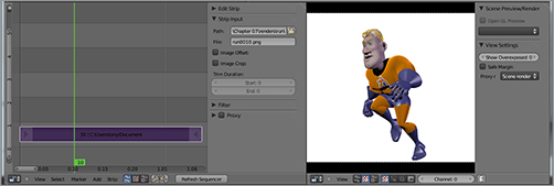
This is all you need to do to prepare to render to a movie file. You can now go to the render buttons and select your output format just as you would for an ordinary render. Select the start and end frames and the size of the picture, and click Animation in the Render panel of the Render properties window. By default, Blender will render the contents of the Sequence Editor if there are any. If you want to render content from the 3D space while there are video strips in the Sequence Editor, you must deselect the Sequence check box in the Post-Production panel of the Render properties window.
Basic Compositing
You can now use a simple compositing feature of the Sequence Editor to drop a new background into the animation. As I mentioned, the background was created and rendered in advance to //renders/background/.
This background animation was created with a very simple use of the array modifier, by the way, which you can find out more about in the references listed in Chapter 18.
Add the background animation images as you added the foreground images: press Shift+A and select all the images in the appropriate directory. Drag this strip to be flush with the previous strip. The channels are displayed bottom to top, and alpha information is not calculated by default. So when you put the new strip in channel 2, you do not see any difference in the display. Channel 1, our Captain Blender animation, is still displayed. You can try moving the strips around to see how this changes when the strips are positioned differently. Placing the foreground animation above the background animation will display only the background animation.
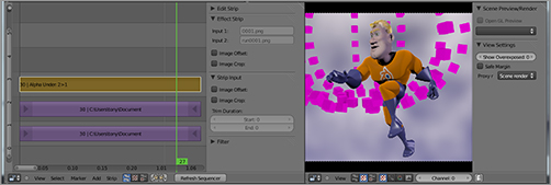
What you want to do is to create an effect strip that combines the two strips in certain ways. Select the foreground strip; then, holding Shift, select the background strip (the order matters here). To add the effect strip, press Shift+A as you would to add any other media. Select Alpha Under from the Effect Strip menu.
The resulting effect strip replaces its component strips in the display and causes the background to show through the zero alpha areas of the foreground. Blender’s default background has an alpha value of zero, regardless of what its RGB values are. The resulting composite looks like the image previewed in .
You can now render the sequence exactly as it appears in the Image Preview window.
A simple composite using Alpha Under
Sound
As you saw in Chapter 8, you can add sound files to the Sequence Editor for syncing. You can create a mixdown from sound files in the Sequence Editor and output this as a single sound file.
In the next chapter, you will take a brief look at Blender’s powerful Python scripting capability and learn how to use currently existing Python scripts to make your job as an animator easier.
Composite Nodes
In addition to enabling you to create node-based materials, Blender’s Nodes system allows you to apply advanced image-compositing techniques that are tightly integrated with the render pipeline. One of the basic sources of input for the Composite nodes is Render Layers. On the Layers tab in the render buttons area, you can separate elements of your image so that they render to different render layers and in that way can be used as separate inputs into the composite nodes. When you select Composite in the render buttons and start a render, the output will be the final result of the network of composite nodes.
To use nodes for compositing, open a Nodes Editor window, toggle the Composite Nodes icon button (the Materials icon button is on by default), and select Use Nodes. When you do this, a render layer input node for render layer 1 and a composite node will appear. You can add new nodes by pressing Shift+A and selecting the node you want from the menu. Here is a very simple nodes setup with two render layers.
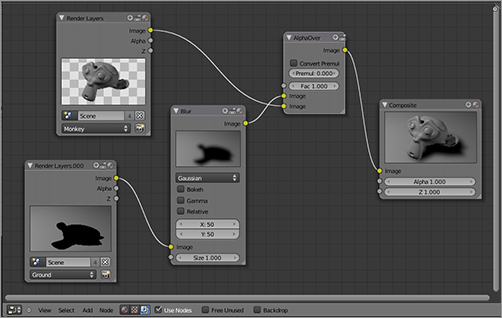
Render layer 1 includes the foreground with the monkey, and render layer 2 includes a plane upon which the monkey rests. These are rendered separately. The output from layer 2 is then used as input for a blur filter node, and the blurred output of this node is used as the backdrop in an Alpha Over node, which lays the monkey render over the background. The output of this node is sent to the composite node, which becomes the final output. The viewer node can be attached at any point to allow a better look at the composite at that point. Both the viewer’s output and the composite image can also be viewed in the UV/Image Editor window.
More detail on using composite nodes is beyond the scope of this book. Check Chapter 18 for pointers on where to go to learn more.

