Chapter 5
Shape Keys and Facial Rigging
Now that you have rigged and skinned the body to an armature so that you can position the limbs, head, and trunk, you’ll turn your attention to some important details of rigging characters. In particular, this chapter focuses mainly on setting up a face so that it can be easily posed to express emotion and to make the mouth movements that are necessary for lip syncing. (You’ll learn how to animate facial expressions and lip sync in Chapter 8.)
There are many ways to go about facial rigging, and this book focuses on an approach that makes heavy use of Blender’s powerful shape key system and driver curves to associate shapes with armature poses. After introducing shapes and drivers and learning about their use for facial rigging, you will also put them to another use: refining the body rig.
- Shape Key Basics
- Building a Shape Key Set for Captain Blender
- Facial Bones and Controls
- Improved Mesh Deformations Using Driven Shape Keys
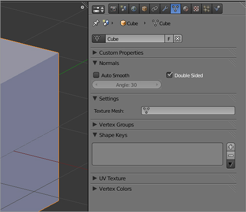
. Click the plus symbol button to the right of the Shape Keys field to create your first shape key. You’ll see a Basis shape key appear, as in .
The Shape Keys panel
Basis shape key
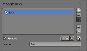
The Basis shape has some unique features, as you’ll see shortly. It represents the shape of your mesh in its “rest” position, unaffected by any of the shape keys you will create. In this case, you made the Basis shape on the default cube, which means that now the vertex positions of that cube shape are represented by the Basis shape.
Now that you have the Basis shape, you can use it to build a new shape. The process is simple:
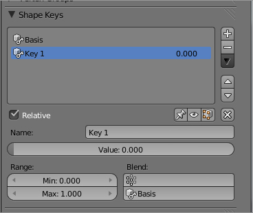
1. In Object mode, click the plus button again. A shape key called Key 1 will appear, as shown in .
Key 1 shape key
2. Enter Edit mode, and edit the shape as you want it by moving vertices. For this first example, select the top four vertices and scale the face, using S followed by Shift+Z to constrain the scaling to the x- and y-axes. Scale the top of the cube down, as in .
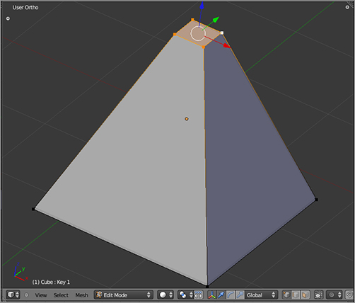
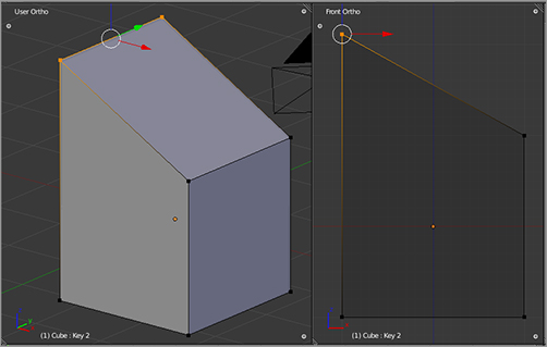
3. Return to Object mode. Now add another key in the same way, Key 2, and edit it to look like the shape in by selecting the edge shown and translating it up along the z-axis.
Editing the first shape
Editing the second shape
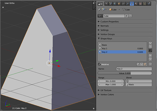
You now have three shapes: the Basis shape and two animatable shape keys called Key 1 and Key 2. Select each of the shapes in the field. You should notice a few things. The first Basis shape is special because it has no slider. Sliders on shape keys represent a gradation from a relative shape (typically the Basis shape) to the shape of the mesh as defined by the shape key. Because the Basis key represents the mesh in its default position, it makes sense for it to have no slider; there’s no difference between it and itself.
By default, the slider ranges from 0.0 (no change from the basis mesh) to 1.0 (full effect of the shape key changes on the basis mesh). Position the slider for Key 1 somewhere between 0.0 and 1.0. You will see the mesh go from the Basis cube shape to the fully tapered shape you created in the Key 1 shape key. You can see how this shape affects the mesh at various levels of influence. But that’s not all. What you are actually seeing when you move the slider back and forth is how all the shapes are simultaneously influencing the mesh. You are seeing the cumulative effect of all the shapes, depending on where their sliders are currently set.
To see how this works, set the slider for Key 1 to 1.0. Click Key 2, and make it the active shape key. If you now slide the Key 2 slider to some value greater than zero, you see the mesh as it is influenced both by Key 1 and Key 2 simultaneously, with both keys exerting influence over the shape of the mesh. You should be seeing something like the shape in .
The mesh with both Key 1 and Key 2 influencing
The fact that you can go from one shape key to another and set each one’s sliders enables you to see how each key is mixing with any and all of the other keys in your shape key set. It also means you should usually keep your shapes’ sliders set at zero while you are creating the shape key set when you are not specifically trying to view them mixed with other shapes to eliminate any possible confusion about what the Basis shape is or what the shape key you’re currently looking at actually looks like. If you forget that one of your shapes is set at something other than zero, you might not see what you expect to see when viewing other shapes. You can reset all the sliders to zero by clicking the little X-shaped icon to the right of the visibility icons above the key’s name field.
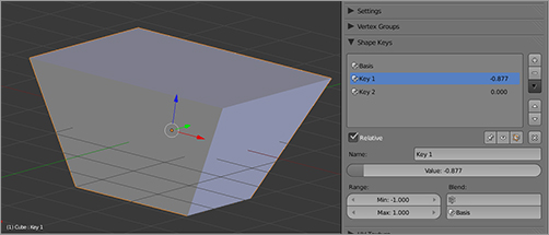
Blender can extrapolate the movement of vertices in shape keys beyond the range of 0 and 1 if you want. Zero is always the basis that the key was created on, and 1 is always the form of the shape that you see in Edit mode when you enter Edit mode with that key active. If you make the minimum value in the shape key’s range less than 0, you can use the slider to go into the negation of the shape. To see an example, go to your Key 1 shape key, and set the Min: value to –1.0. Now the slider extends down past 0. Move the slider down to see what the shape looks like with the negation of Key 1 active. As you can see in , the shape you see is the “reverse” of the pyramid shape you made for Key 1. Likewise, you can extend the positive change of the shape key by increasing the Max: value beyond 1. Before you continue with this section, put the Min value for Key 1 back to 0.
Key 1 shape at a negative slider value
Additivity
The shape keys you are using work by adding their relative coordinates. This is an important concept to get a handle on if you will use blended shapes.
To see an example of this in action, make sure that all your shape keys are currently set to zero; then select Key 1. Move the slider to 1.0. Click the plus symbol to create a new shape key, which will be called Key 3. Key 3’s shape will now be a copy of whatever shape was visible in the 3D viewport when you added the shape key. In this case, that means Key 3 will be a copy of Key 1. If you set Key 1’s slider to 0.0 and set Key 3’s slider to 1.0, you will see this.
However, if both shape keys are set to nonzero values, the effect is cumulative. This may be what you want, but it may cause problems if you are not careful. For example, if you set Key 1 to 1.0 and set Key 3 to 0.7, you will see the undesirable effect shown in .
Additive effect of Key 1 and Key 3
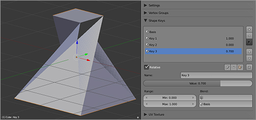
Although Key 1 and Key 3 are the same shape, their cumulative effect is not the same because of additivity. It’s important to be careful of this when creating facial shapes that you intend to blend together. If two shapes have a redundant effect, you can wind up with some undesirable additive effects.
Adding and Deleting Vertices
Shapes record the positions of verts within a mesh. The verts and the edges that connect them are properties of the mesh itself, so they can be added or deleted in Edit mode. They are not specific to a particular shape, however. If you add verts in a shape, they will also exist in all the other shapes you have defined. In principle, their position should be unchanged from the position in which they were created; you will have to specify their location separately for each shape in that shape key’s Edit mode. However, significant mesh edits that change the topology of the mesh will confuse Blender and can wreck your shape keys completely. In practice, you are better off planning not to do mesh edits involving creating or deleting verts after you have started creating shapes.
Basis Key
The Basis shape is special in some respects and not in others. It is not keyable, so it has no slider. However, in most other respects it is about the same as any other shape key. It can be deleted; if you delete the Basis, the next shape key down in the list of shapes (probably the first one you added on top of the basis) will pop up to the Basis shape key position, and its slider will disappear. In this case, your original base mesh shape will also be lost, and whatever you had in Key 1 will take its place. You can change the name of the Basis key, but you will probably never have a reason to do so. If you change the Basis shape by moving vertices around, these changes will be automatically reflected in other shape keys.
Finally, insofar as the Basis shape key is special at all, it is only special by grace of its being the first shape you create and therefore the first shape key in your set. In fact, the order of shape keys can be rearranged, and any shape key can be the first. In this case, the shape key named Basis will no longer be the true basis key, and it will have acquired a slider. However, because keys represent relative changes, the Basis key’s slider will not change the shape of the mesh. I cannot imagine any circumstance for which this would be desirable, but because keys might become shuffled accidentally, you should know how to put them back in order. To reorder the shape keys, simply use the up and down arrow buttons to the right of the shape keys’ names in the Shape Keys field, or use the keyboard up and down arrow keys while the mouse pointer is over the shape key area.
Shape Key Drivers
Shape key drivers are crucial to the way you will rig Captain Blender’s face, so it’s necessary to introduce them before continuing.
Drivers are related but distinct from the F-Curve animation curve system that you will read about more in Chapter 6. They are similar insofar as they represent mathematical functions and can be viewed in Blender’s Graph Editor. Drivers are probably the most technically demanding aspect of Blender to work with that I will discuss in this book, in that they do require a little bit of math. If you passed your high-school math classes, you should be OK (and if you haven’t, then getting your head around drivers should give you a good head start!).
A function curve, whether it be an animation F-Curve or a driver, is a representation of some value that changes depending on some other value. In the case of animation F-Curves, the value changes according to time, resulting in animation. In the case of drivers, you can set a value to change as a function of any other changing value. As one value changes (for example, the rotation of a specific bone), another value changes (such as the slider value of a shape key). In this case, you would say that the shape key is driven by the bone’s rotation.
Setting Up a Driver
You’ll set up a very basic shape key driver now by using the shapes you have just created:
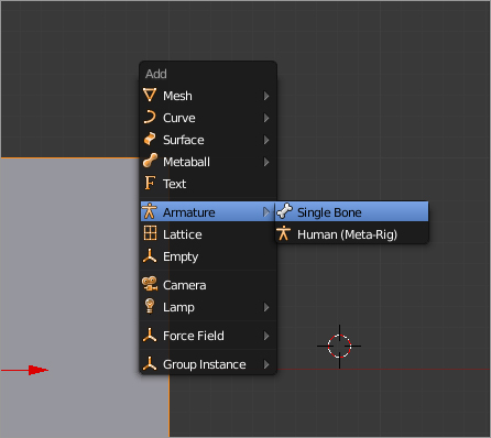
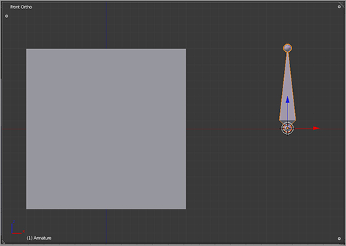
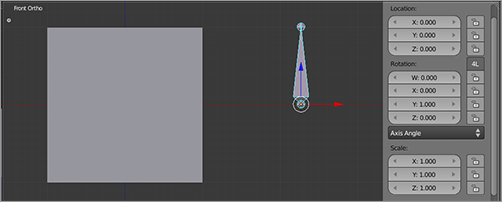
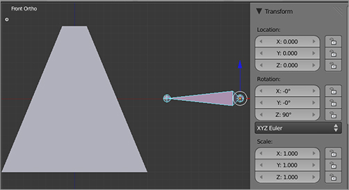
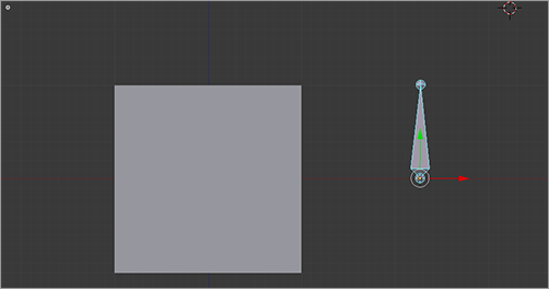
1. In Object mode, add an armature object to the side of the default cube by pressing Shift+A and selecting Armature ⇒ Single Bone, as shown in . The resulting armature should look as shown in .
Adding an armature
Default cube and a single bone armature, front view
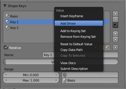
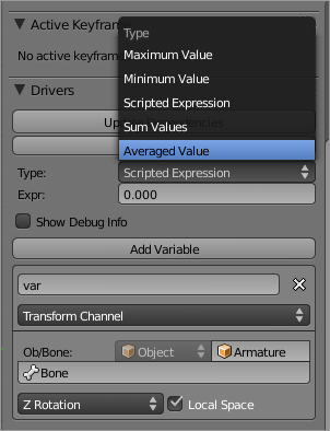
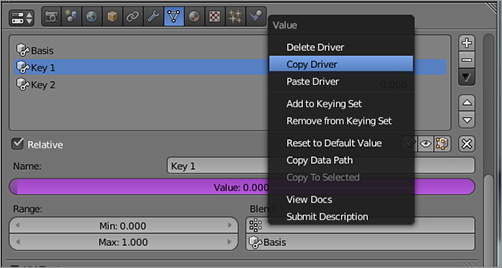
2. Select Key 1 in the Shape Keys field, move the cursor over the numerical value to the right of the shape key name, and right-click to bring up the menu shown in . Choose Add Driver from this menu.
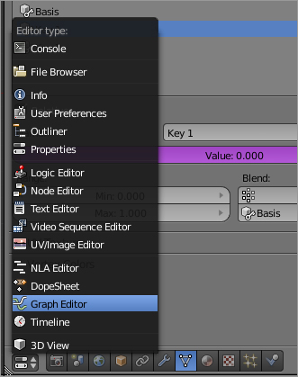
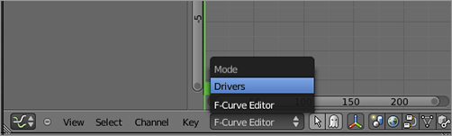
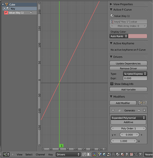
3. To see the driver, you will need to open a Graph Editor window using the Editor Type drop-down menu, as shown in , and then choose Drivers from the Mode drop-down menu in the header in the Graph Editor window, as shown in . The driver is displayed, as shown in . In the left side of the window you can select available drivers. The middle area is the graph viewer proper, where the driver function curve is displayed, and the Properties Shelf in the right of the window (toggled with the N key) displays the driver properties in detail.
Choosing Add Driver from the Value menu
Opening a Graph Editor window
Entering Driver mode in the Graph Editor
The driver displayed in the Graph Editor
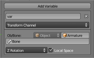
4. The driver you will create will depend on a variable representing the rotation of the bone. Any time a driver of any kind depends on a value, this value must be encoded as a variable for the driver. Set up the variable as shown in . Choose Transform Channel for the variable type, Armature from the Object drop-down menu, and Bone in the Ob/Bone field that appears. Choose Z Rotation from the drop-down of transform channels, and select the Local Space check box.
Setting up the Transform Channel variable
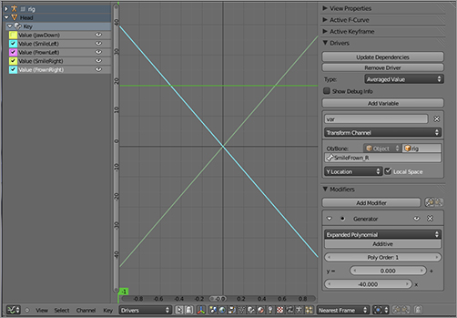
5. Choose Averaged Value from the Type drop-down menu, as shown in .
Selecting Average Value as the driver type
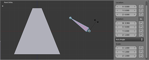
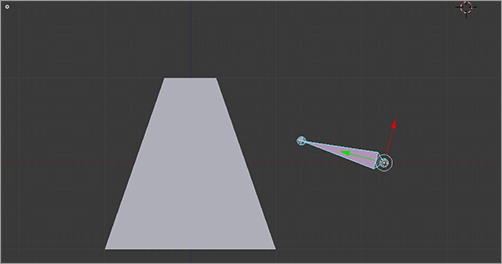
6. Test the driver by rotating the bone in pose mode, as shown in . You should find that the bone rotation corresponds to the activation of the shape as shown in the figure. You’ve now completed a very basic shape key driver.
The basic shape key
Tweaking the Driver
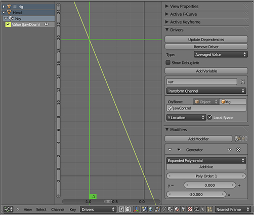
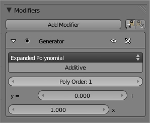
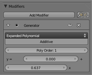
Although the driver you created in the previous section works, the relationship between the rotation and the shape key activation may appear arbitrary. In fact, it is a one-to-one relationship, by default, as defined by the polynomial equation in the Generator Modifier panel on the Properties Shelf of the driver, shown in . But what are the units of this one-to-one relationship? The y-axis represents the shape key’s activation, ranging from 0.0 to 1.0. The x-axis of the graph represents the rotation of the bone around its own local z-axis in radians. This may be a bit unexpected, because in most places in the Blender interface, angles are expressed in degrees.
A Generator modifier describing a one-to-one relationship
If it’s been a while since you did trigonometry and you’re not a programmer, you may be hazy on radians. Radians are simply a unit of measuring angles, just like degrees are. A full circle is 2 * pi radians. Pi is approximately 3.14, so one radian represents an angle a bit less than a sixth of the way around the circle. The angle of the bone in the earlier figure is about one radian in the counterclockwise direction. Radians have mathematical properties that make them very good for calculating functions relating to circles, so most programming languages express angles in radians under the hood. However, they are difficult for humans to work with for several reasons, a big one being that the number of radians in a circle isn’t a nice integer. Degrees are much easier for people to work with because full circles, half circles, quarter circles, and eighths of a circle can all be expressed with integers.
If you want to make your driver a bit more intuitive and have it use right angles, then you’ll need to do a bit of math and think a bit in radians. Since there are pi radians in a half circle, for a shape key driver with a y range of 0 to 1 over a half-circle rotation, you’ll need the x to range from 0 to pi. So, the question to ask is, what number when multiplied by pi yields 1? The answer, of course, is 1/pi.
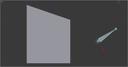
Let’s say you want the bone to drive the shape key over a 90-degree rotation. In this case, the bone rotation needs to have twice the effect that it would in the case of a half-circle rotation, so the number to multiply x by is 2/pi. You can actually enter this directly into the x coefficient field in the polynomial panel verbatim as 2/pi, and Blender will calculate the result, which is displayed as 0.637, as shown in . When you rotate the bone 90 degrees counterclockwise, the shape will be at its maximum point, as shown in .
The polynomial for a 90-degree driver
The shape key driver bone rotated 90 degrees
You’ve now created your first driven-shape driver. To make more drivers, you can follow the same steps or take a shortcut by copying and pasting drivers from one shape to another. To do this, right-click the numerical value of the key from which you want to copy the driver, and choose Copy Driver from the menu, as shown in . Then right-click the numerical value on the key you want to copy the driver to, and choose Paste Driver.
Copying a driver
Do this to copy the driver of Key 1 to Key 2, and then edit the new driver as shown in so that the x coefficient is negative (–0.637) rather than positive. The resulting pair of drivers will control the two shape keys, as shown in .
Editing the x coefficient for the new driver
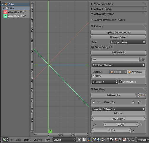
The two drivers in action
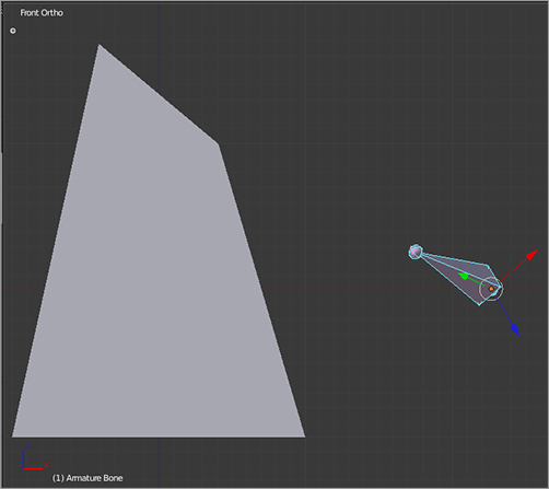
The drivers can also be independent of each other, simply by associating them with independent values. Edit the Key 2 driver again, and change the Transform Channel value from Z Rotation to X Rotation. When you do this, you will be able to control the taper shape with the z rotation of the bone and the wedge shape with the x rotation of the bone. Rotating the bone in both directions at once will activate both shapes simultaneously, as shown in . Experiment with double R key trackball rotation by pressing R twice to rotate the bone.
Two independent drivers
After you set up drivers for the shapes, the driven shapes can no longer be independently controlled with the shape sliders, but if you create a new shape on the basis of a driven shape, the new shape can be controlled independently with its own slider.
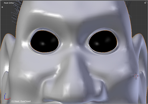
, and pressing H. The selected vertices should disappear, leaving you with the front of the face, as shown in . (To unhide all vertices, simply press Alt+H.)
Selecting vertices to hide
The head with vertices hidden
To create shape keys, click the plus icon to the right of the Shape Keys field in the Properties window, just as you did in the previous section. First create a Basis key.
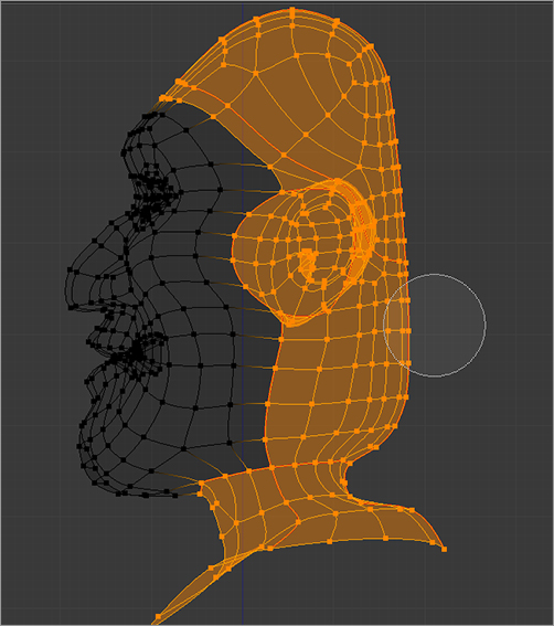
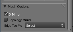
Click the plus icon again to create a new shape key. Change the name of the new shape from Key 1 to EyesClosed. Now enter Edit mode. There is no longer a Mirror modifier on this object, but it would be nice to have your edits mirrored. Fortunately, you can do this with the X Mirror option under Mesh Options in the Tool Shelf on the left side of the 3D viewport (see ). X Mirror will work as expected only if your mesh is symmetrical to begin with. That is, it will work only on symmetrical parts of your mesh. It will also not mirror changes to the topology of the mesh. You cannot mirror extrusions, cuts, or deletions in this way.
X Mirror editing
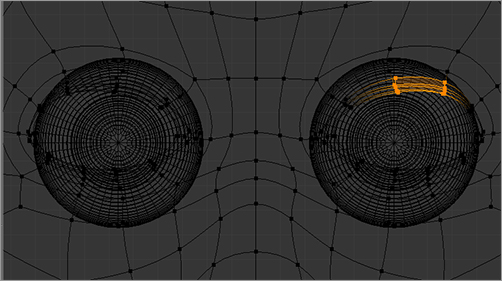
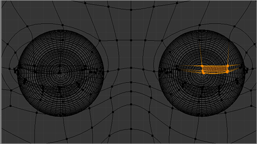
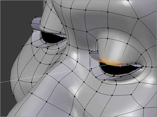
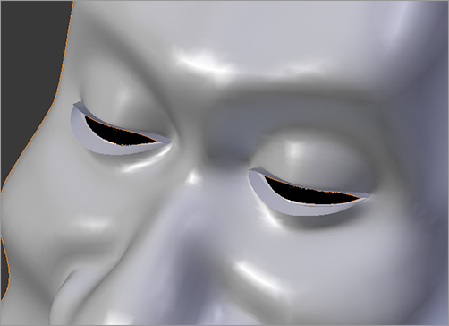
With X Mirror active, select and edit the top eyelid, as shown in , moving the necessary vertices downward along the z-axis. To select these vertices, use the Circle Select tool (press C). To unselect vertices, use Circle Select while holding down the Alt key. The middle vertices of each eyelid should move down farther than the others. The closed eyelids should extend just around two-thirds of the way down the eye. Be sure that you have selected the verts of the eyelashes, too, to be sure that the eyelashes move along with the eyelids. You also need to make sure that the eyelids move forward along the y-axis so that the eyeball does not poke through the eyelids. Adjust the eyelids along the y-axis in Solid mode so that you can see what’s happening with the eyeball, as in .
Selecting and editing vertices in the eyelid
Fixing the eyelids along the y-axis
The process is the same for the bottom eyelid. Bring the pertinent vertices up to meet the top lid, being sure to also include the eyelash vertices.
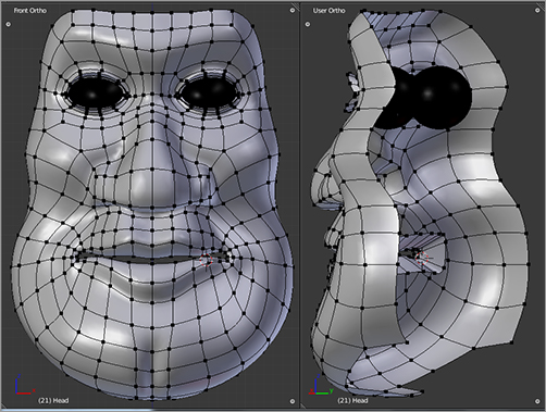
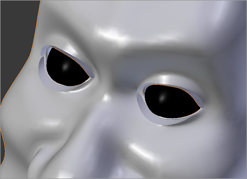
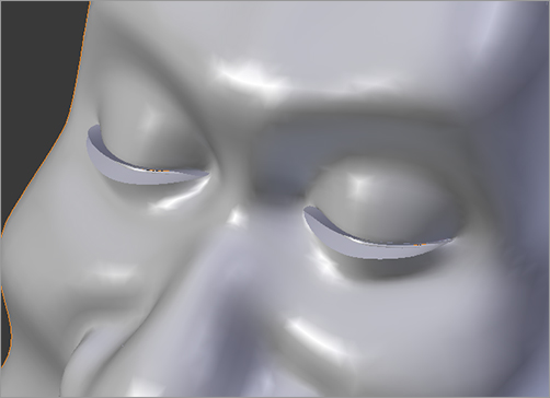
When you’re satisfied with your closed eyes shape, return to Object mode. You should be sure to check the shape at several different points between 0 and 1 to make sure that its full range of motion is clear of problems. In , you see the EyesClosed shape as it appears with slider values set at 0.25, 0.5, 0.75, and 1. No problems appear. (Characters with protuberant eyes might require a slightly different set of shape keys to take their extreme curvature into account—for example, a basis with the eyes partially closed, one fully closed, and the final one fully open.)
The EyesClosed shape key at four values
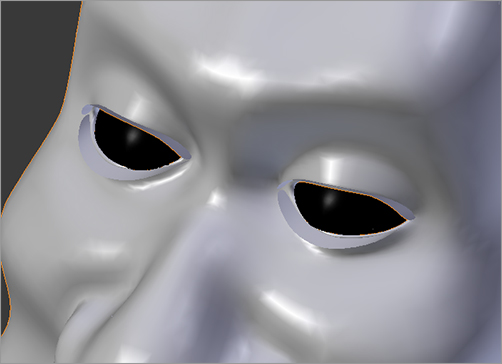
Finally, you’ll make use of the shape key’s range settings to get a little bit more from this shape. In Object mode, change the Min value of the EyesClosed shape from 0 to –.25. You now have a bit of room on the slider to move in a negative direction, which gives you the wide-eyed shape shown in for free.
Eyes wide open
Asymmetry
It can be convenient to model many shapes symmetrically using X Mirror editing. However, humans do not move symmetrically, either in body or in face. To be able to control different halves of the model separately, you must split the shapes into separate keys. Fortunately, it’s not difficult to convert symmetrical shapes to asymmetrical shapes; you can use vertex groups. You create two vertex groups, one representing Captain Blender’s left side and one representing his right side. You’ll then make copies of the shape keys and apply them to each vertex group separately.
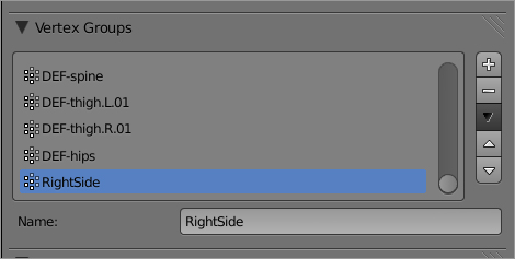
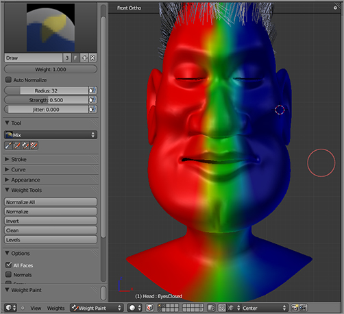
To create a new vertex group, click the plus icon to the right of the Vertex Groups field in the Properties window. Name the new group RightSide, as shown in . Enter Weight Paint mode, and paint the head so that the right side of the head is solid red (1.0), the left side is solid blue (0.0), and a streak down the middle is green (0.5), as shown in .
Adding the RightSide vertex group
Weight painting the RightSide vertex group
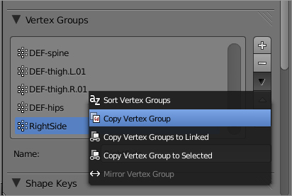
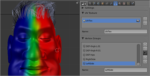
Copy the RightSide vertex group by clicking the black triangle icon to the right of the Vertex Groups field to open the menu shown in and selecting Copy Vertex Group. Rename the new vertex group LeftSide. Tab into Edit mode, and mirror the vertex group values using the same menu you used to copy the vertex group (for unclear reasons, the Mirror Vertex Group menu item is active only in Edit mode). The resulting mirrored vertex group will appear as shown in in Weight Paint mode.
Copying a vertex group
The LeftSide vertex group
Now that you have the RightSide and LeftSide vertex groups defined, you can use them to create asymmetrical shape keys. To create asymmetrical keys for the EyesClosed shape, do the following:
1. In Object mode, with the mesh selected, go to the Shape Keys field, and select EyesClosed as the active shape. Set the slider value to 1.0. The shape in the 3D view should be displayed with the eyes fully closed.
2. Click the plus icon to the right of the Shape Keys field to create a new shape key. You have now created an identical copy of EyesClosed. Name this shape EyesClosed.L. In the VGroup field, enter LeftSide. The shape is now restricted to the LeftSide vert group. Return to the EyesClosed shape, and set the slider value back to 0.0.
3. Repeat steps 1 and 2 to create the EyesClosed.R shape key applied to the RightSide vertex group.
Adding a new key will always create a key the shape of whatever shape is active and visible in the 3D viewport. If you add a key while another key is active that has an associated vertex group, the new shape key will be a copy of the original key as applied to the vertex group, but the new key itself will not have a vertex group associated with it. For example, if you copy EyesClosed.L, the new key will affect only the left eye, just as with the original but without the need of a vertex group to limit it. You can use this fact to copy portions of shape keys by creating temporary vertex groups covering the area of the shape key you want to duplicate, applying the vertex group to the shape key you want to duplicate part of, and then copying the shape key with that vertex group applied. The new shape key will differ from the Basis key only in the places covered by the vertex group. This method is also useful for breaking a single facial expression into component shapes. For example, you can create a single “angry” face and then use this method to create separate shapes for different parts of the face, which can then be blended together as you saw in this chapter. It is also possible to use weight painting to see the different shapes blend in real time.
Shapes for Lip Syncing
The main references for lip syncing in animation are variations on Preston Blair’s original phoneme set. In the excellent book Stop Staring (Sybex, 2003), Jason Osipa recommends breaking phoneme shapes (and all other expressions) down into more basic component parts, such as vertical stretching of the lips, which are designed specifically not to be used alone but to form lip positions in conjunction with other shapes. Because the main point here is to illustrate how this all works in Blender, I remain somewhat agnostic with regard to optimal shape key sets and cover a middle road between phoneme shapes and component shapes. Still, I cover the main lip positions, which I’ve described in .
Lip positions
| Phoneme | Position |
| A, I | Formed with the mouth in a fairly relaxed and open position. |
| E | The lips are stretched wider than A and I, but the jaws are much more closed. Teeth are very visible. |
| O | The mouth is rounded and somewhat open. |
| U | The mouth is rounded and is less open than with O, and the lips protrude somewhat. |
| C, D, G, K, N, R, S, T, Th, Y, Z | These phonemes are mostly articulated inside the mouth, so the lips do not distinguish them much. The mouth is somewhat more open than with E, the lips are less wide, but the teeth are still quite visible. |
| F, V | The bottom lip folds in and connects with the top teeth. |
| L, D, T, Th | The mouth is almost as open as A and I, so the articulation of the tongue is visible. This is an option for phonemes that are articulated with the tongue. |
| M, B, P | The lips are shut tightly. For plosives such as B and P, they might also curve in slightly before opening suddenly. |
| W,Q | This is like U, only more tightly puckered. |
| Rest | This is a relaxed position that serves as a pause between phonemes and a transition point from certain phonemes to others. |
Because you are dealing with blend shapes that can be combined to create phoneme positions, you will not have a one-to-one correspondence between shapes and phonemes. But it should be clear how the shapes you build can be combined to create the phoneme positions listed.
The creation of these shapes itself is straightforward. You can follow the instructions in the previous section for creating, naming, and editing new shape keys. The modeling of these shapes should be limited to moving existing vertices around. Some suggestions for facial shape modeling include the following:
- Model symmetrically. Use x-axis mirroring when you can.
- X-axis modeling works only on meshes that are already symmetrical, and it can be sensitive to subtle asymmetries. It might work with some vertices in a mesh but not with others, if the vertices do not already perfectly mirror each other. So when using x-axis mirroring, keep a good eye on both sides to make sure that all the vertices that you want to move are actually moving.
- For vertices that you cannot edit with X Mirror editing, you can approximate mirrored editing by selecting both sides simultaneously and constraining all transforms to specific axes. You can approximate mirrored translating in the X direction by scaling along the x-axis to move the vertices apart or together.
- You will often select vertices in wireframe mode, and this is much easier to do if you have hidden vertices that are not relevant to the shape you’re editing. Use the H key to hide vertices that you are not working on.
My set of lip shapes is illustrated and described as follows. Note that with lip sync shapes there is no need to make asymmetrical copies because speech is one of the few more or less symmetrical things that human beings actually do. You can always add whatever slight asymmetry you might want in the mouth by mixing in shapes from the next section. The set of shapes is as follows (Basis is not shown):
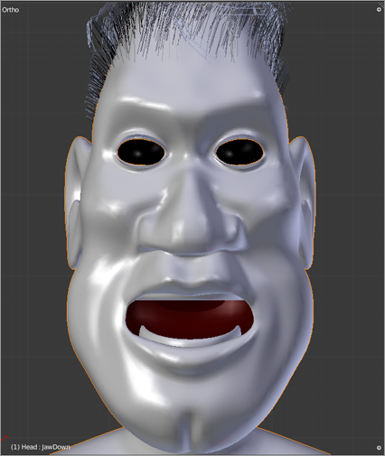
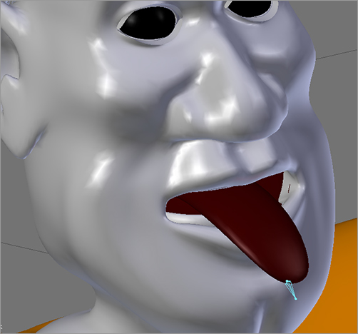
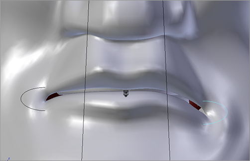
Jaw Down Create this shape by selecting the jaw and chin area of the main mesh; also select the tongue and the bottom row of teeth using the L key. In side view, locate the cursor slightly below the ear where the jawbone forms its hinge with the skull; then, using the cursor as the pivot point, rotate the jaw down into an open position.
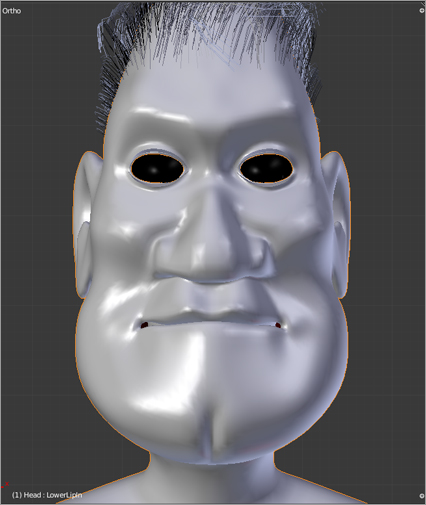
Lower Lip In Select verts on the outside and inside of the lower lip, raise slightly and move inward slightly on the y-axis, and also rotate slightly back around the x-axis. Verts below the lip should be moved out and upward slightly to indicate where the teeth would be pushing against the inside of the lip (below left).
Upper Lip In Similar to lower lip in but with the vertices of the upper lip rotated downward around the x-axis (below right).

Lower Lip Out Select the same verts as lower lip in, but move them forward and curl the lip slightly downward (below left).
Upper Lip Out Similar to the previous poses, but the upper lip protrudes and curls upward slightly (below right).


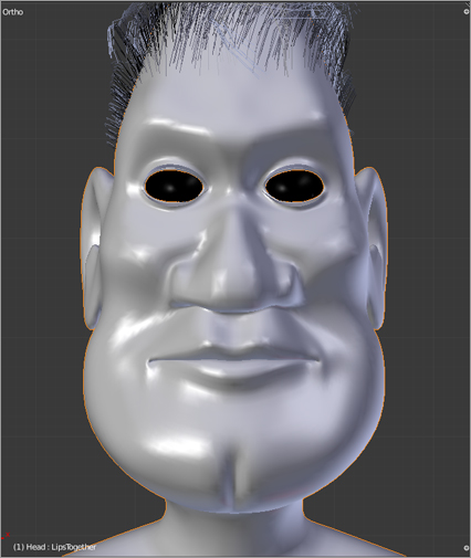
Lips Together Similar to the rest pose, but with the lips fully together. Blended with lower and upper lips in, this will give a tightly pursed position (below left).
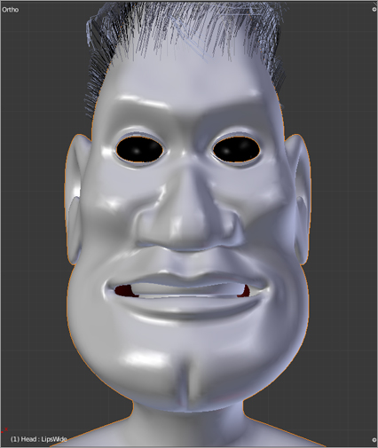
Lips Wide Teeth together and lips widely spread; at its maximal point, the teeth are fully bared. Simply select and move the verts of the lips to form the shape (below center).
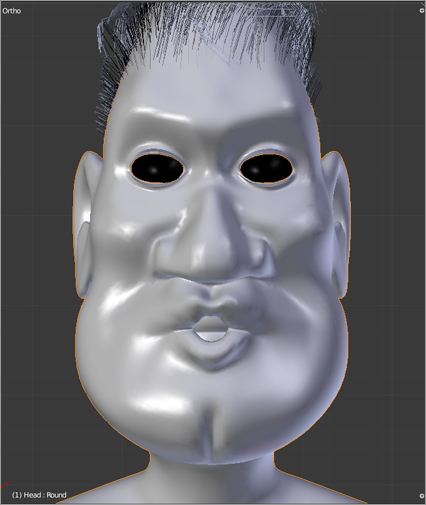
Round Lips are parted vertically and brought together horizontally to form an O shape. Pushed slightly past its maximum and blended with upper and lower lips out, this shape will form a tight pucker. Again, creating this shape is basically a matter of selecting and moving the lip verts until you are happy with the shape (below right).
This collection of shapes and the various blended positions you can get with them, in conjunction with the tongue rigging you will see later in the chapter, provide you with all you need for basic lip syncing.
Shapes for Expressing Emotion
There is no hard and fast rule about what shapes are necessary to give a character a full range of emotional expressiveness. The most expressive parts of the face are the areas surrounding the eyes, so it is necessary to have a range of shapes to control eyelid movement, eyebrow movement, and some upper cheek movement. The mouth is, of course, important for smiling and frowning, but the sincerity of smiles and frowns has at least as much to do with the eye area as the mouth. Also, with mouth movement, the crease running down from the flap of the nose to the edge of the mouth is important to emphasize the smile. A smile that does not affect the cheek and the area around the nose appears unnatural.
The modeling suggestions for lips hold for these shapes, too. I modeled them all symmetrically first; I then made asymmetrical copies where necessary using the RightSide and LeftSide vertex groups.
It is certainly important to have separate discrete shapes for different parts of the face that you can blend together to create expressions. However, there is a lot of flexibility in how you create these shapes. One common approach is to model full expressions in advance and then isolate small component shapes using the vertex group technique referred to previously. This ensures that the component shapes work well together to create complete expressions and reduces the chance that their additive properties will conflict with each other. For the sake of expediency, I did not take the extra step of creating full expressions in advance; I modeled component facial movements directly.
The shapes are described here:

Brows Together This shape is actually formed less by the eyebrows coming together (although they do, slightly) than by the wrinkles forming between the brows. You form the wrinkles by bringing neighboring edges forward and back along the y-axis and emphasizing the depth of the wrinkles by moving the edges closer together. This shape is usually used in conjunction with other shapes to create a range of eyebrow movements, often indicating concentration, anger, or fear. It is not possible to knit only one brow, so there is no need to make right and left copies for this shape (right).
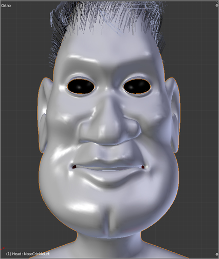
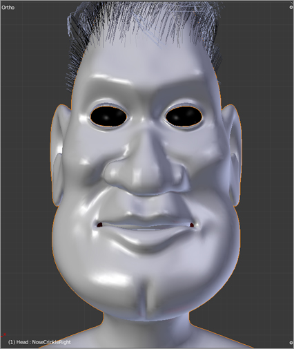
Nose Crinkle (Left and Right) Raise the flap of the nostril while pushing the crease around the nostril deeper and bringing the cheek slightly forward, further emphasizing the crease. The wrinkle at the bridge of the nose can also be included in this shape. This shape occurs in a variety of expressions; it is very pronounced in expressions of disgust and some angry expressions, but it also will have an effect in a big smile (below).
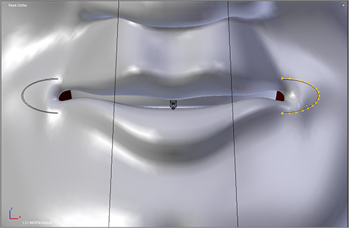
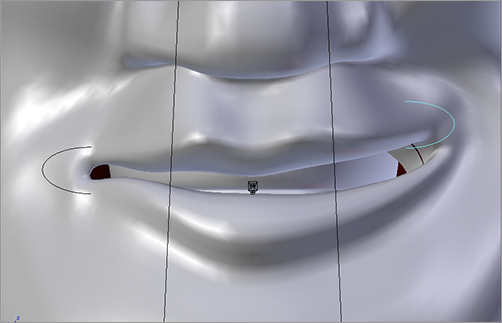
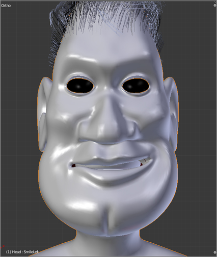
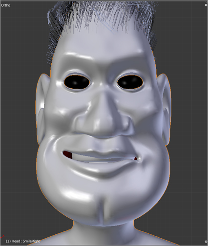
Smile (Left and Right) The edges of the mouth are raised and rotated slightly. The crease from the nose is deepened, and the cheek is brought forward slightly. This mouth shape is an important component of a smiling expression, but it is not the only one. It must be mixed with appropriate movements of the cheeks, the nose, and the area around the eyes to convey the desired emotion.
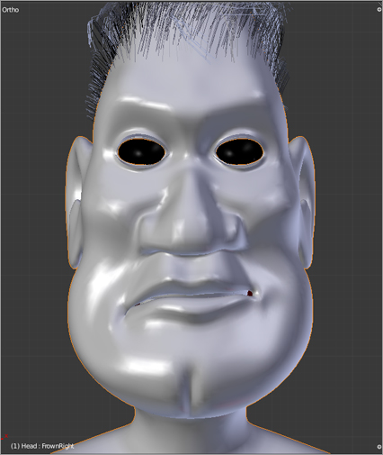
Frown (Left and Right) Edges of the mouth are brought down and rotated slightly. This shape is often used with expressions of dismay, sadness, or anger.

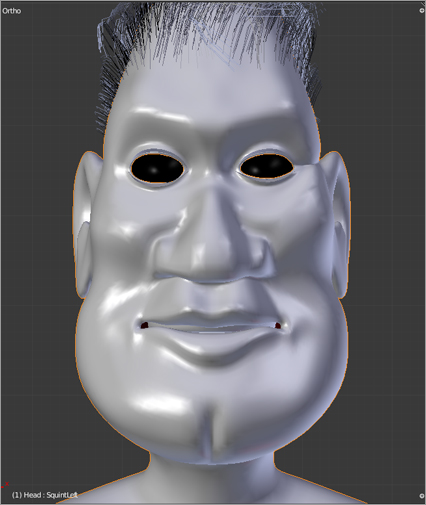
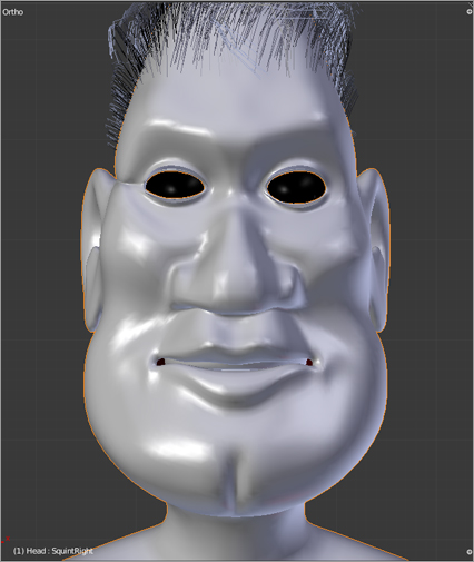
Squint (Left and Right) The crease at the edge of the eye is emphasized, and the cheek is raised. In addition to being used to indicate concentration (or of course physical difficulty seeing something), a squint is also a component in a big smile.
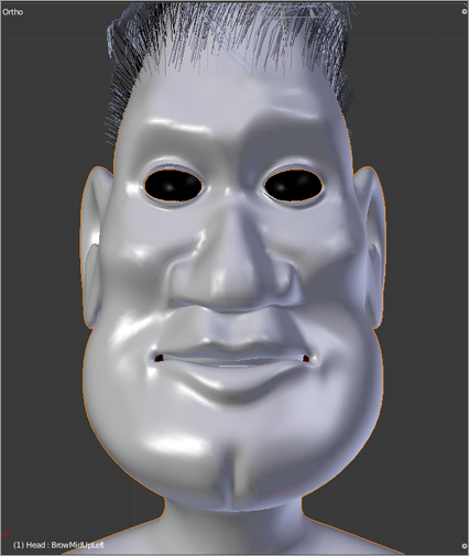
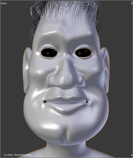
Brow Middle Up (Left and Right) The portion of the brow over the nose is raised, and forehead wrinkles are emphasized. This shape is often used in expressions of worry or fear.
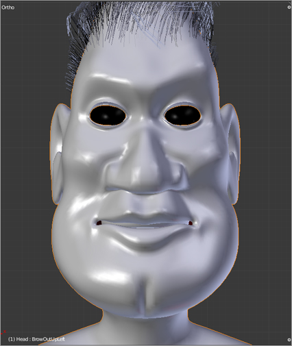
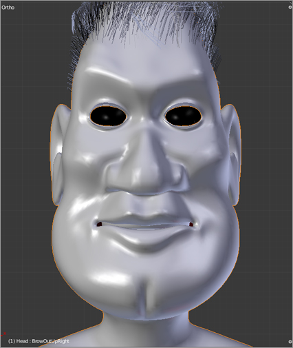
Brow Outside Up (Left and Right) The portion of the brow farthest from the nose is raised, and forehead wrinkles are emphasized. This shape is often used in expressions of delight, surprise, or disbelief.
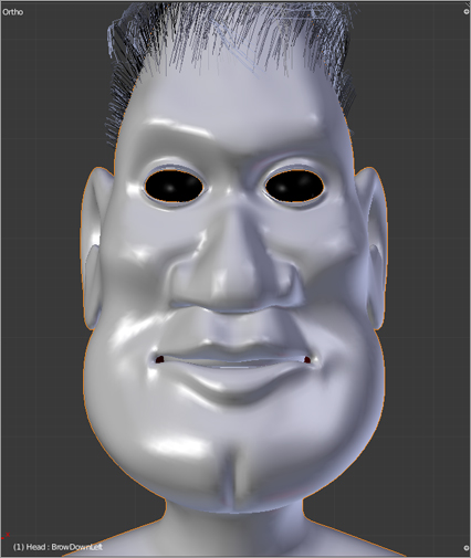
Brow Down (Left and Right) The entire brow is brought downward. This shape is often used in conjunction with the brows together shape and can indicate anger, concentration, and (when applied asymmetrically) suspicion.

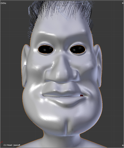
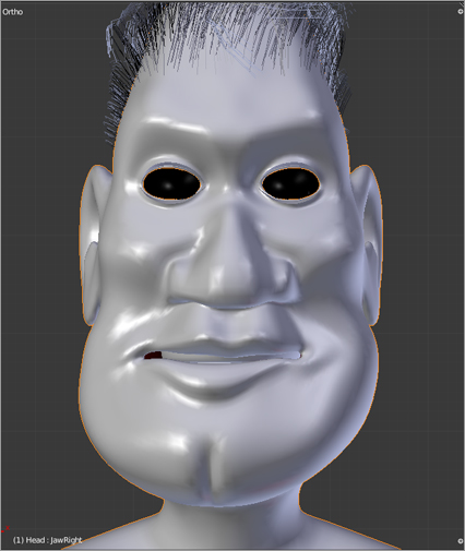
Jaw Left/Jaw Right The same jaw area that drops in jaw down is moved slightly from side to side. It is an emotionally very neutral shape that can be applied to add variation to a lot of different expressions and often is part of a thoughtful expression.
You now have a pretty complete set of facial poses to create facial animations with. In the next section, you will see how to associate these various shapes with driver bones so that when you get to animating, you can control everything by using a well-organized set of armature controls.
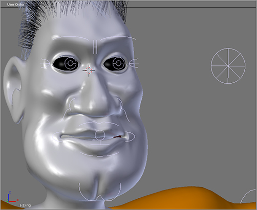
. Name the bones Eye.L and Eye.R.
Eye bones
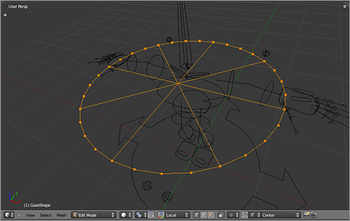
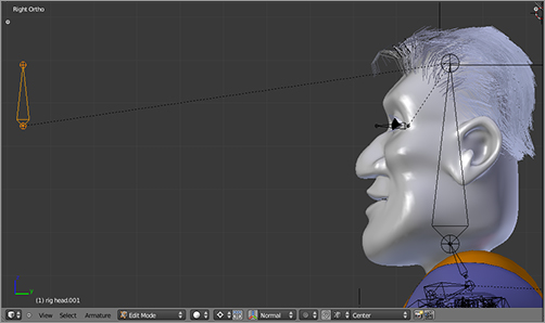
4. Extrude a bone from the head bone. Select this new bone, and press Alt+P to disconnect the bone from its parent. Move the new bone some distance out ahead of the face along the axis, as in . Name this bone Gaze.
Gaze bone
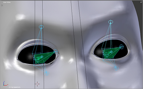
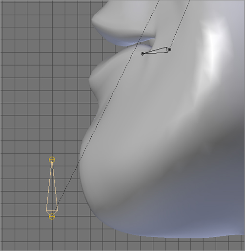
5. With the armature still in Edit mode, snap the cursor to the base of the left eye bone. In side view, copy the bone by pressing Shift+D, and rotate the new bone up about 30 degrees (the cursor should still be selected as pivot point). Name this bone UpperLid.L. Copy the eye bone again, and rotate it downward about 30 degrees. Name this bone LowerLid.L. Now copy the eye bone one more time, and scale down to about 50 percent of the size of the eye bone without rotating or changing the location at all. This should be called LidMove.L. Parent UpperLid.L and LowerLid.L both to LidMove.L, making them both unconnected children of that bone. Parent LidMove.L to HeadDeform. You should now have a setup like the one in . Do the same on the right side.
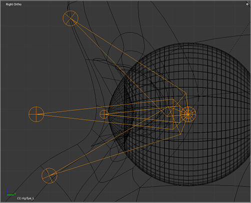
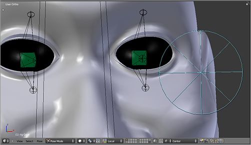
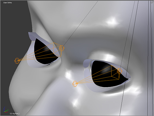
6. In Pose mode, you need to set up two types of constraints on each eye. First, set up an IK constraint on the Eye.L/R bones, with the target the Gaze bone. (You could use a Track-to constraint, but doing so might introduce some unwanted incidental rotations, so for this case I find IK the simpler option. The intention is the same.) Make sure to set the IK chain length to 1. Your eye bones should now follow the movement of the Gaze bone.
7. The second constraint you will set up is a copy rotation constraint on LidMove.L/R with the target as Eye.L/R, respectively. However, you do not want to copy the rotation on all axes. You want the eyelids to move up when the eye rolls upward, and you want the eyelids to move down when the eye rolls downward, but you do not want the eyelids to move from side to side when the eyeball swivels to the side. So, you must make sure that the local x-axis button only is selected and toggle the other axis buttons off in the Copy Rotation constraint panel. You should now be able to move the Gaze bone around and have the Eye.L/R bones follow its movement, whereas the eyelid constructions go up and down in response to vertical movement of the Eye.L/R bones, as in .