Chapter 4
Armatures and Rigging
Most 3D character animation, both CG and traditional, relies on armatures to manipulate the characters’ body parts. Armatures behave as the characters’ skeletons, and their segments are referred to as bones. Of course, the mechanics of motion and posing are very different for a 3D mesh than they are for a flesh-and-blood human, so the bones of a CG character do not generally correspond to actual bones in a live person. Nevertheless, they are very similar conceptually. Building an armature can be very simple or very complicated, depending upon how much control the animator wants over the character’s body parts and how many constraints and restrictions are desired on the character’s movement. An armature in which the knees can be bent sideways, for example, is likely to be a simpler armature than one in which the joints have natural limitations. The degree of complexity necessary in an armature depends upon the requirements of the animation. A good armature should result in an easy-to-manipulate character with convincing movements.
The process of rigging a character means setting up an armature and its associated constraints. Skinning refers to connecting a mesh to an armature so that manipulating the armature results in the desired deformations of the mesh. The mesh should follow the movement of the armature in the appropriate way. Simply put, this is accomplished by having each bone influence the movement of certain vertices. There are several ways to assign influence to vertices, which are discussed in this chapter.
- Blender Armature System
- Building a Simple Armature
- Rigging Captain Blender with Rigify
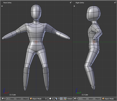
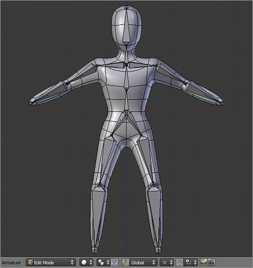
. If you followed the modeling tutorials in Chapter 2, you should have no problem box-modeling the figure yourself. If you prefer to skip the modeling, you can find the mesh of this figure on the accompanying DVD, in the file figure.blend. In the following example, front view is the view displayed by pressing 1 on the number pad, top view is the view by pressing 7 on the number pad, and pressing 3 on the number pad displays the view of the figure from the user’s right, as in the other examples in this book.
A simple 3D figure
Later in this chapter, you’ll see a much faster and easier way to create sophisticated rigs using Blender’s Rigify system. However, in this simple example, you’ll build the rig from scratch in order to understand the basics of how armatures work.
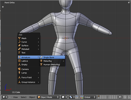
The first step is to create the armature. The 3D cursor should be placed at the center of the Mesh object. In Object mode, press Shift+A, and select Add ⇒ Armature ⇒ Single Bone, as shown in . If the cursor was not in the center of the space when you added the object, simply press Alt+G to move the object to the origin of the 3D space.
Adding the armature object
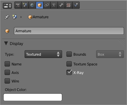
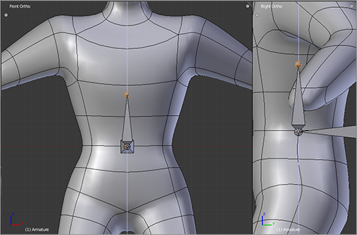
Although the armature is there, you will not be able to see it in solid view mode, because it is located inside the mesh. With the armature object selected, select the X-Ray box in the Object Properties panel, as shown in . This will ensure that the armature is visible even if other objects such as the character mesh cover it. When you’ve done this, the bone should be visible, as shown in .
Setting the object properties to X-Ray display
Editing armatures and bones is analogous to editing most kinds of objects in Blender. The G, R, and S keys have the same effect of translation, rotation, and scaling as they do elsewhere. Likewise, the E key is used to extrude when in Edit mode, which in the case of bones creates a new connected bone from the tip or the root of the original bone. To begin editing the armature, enter Edit mode either by using the menu in the 3D viewport header or by pressing the Tab key.
HOTKEY: Pressing E extrudes new bones in an armature in Edit mode.
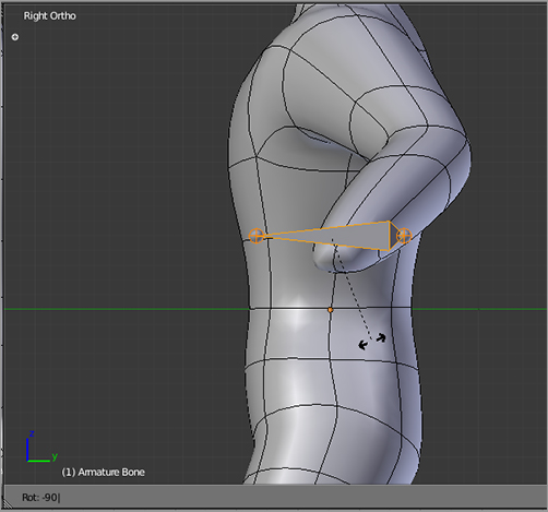
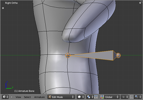
In Edit mode, switch to side view (Numpad 3), select the whole bone by clicking its middle portion, and rotate the bone 90 degrees counterclockwise by pressing the R key and entering -90 directly, as shown in . Press the G key to grab and move the bone so that the tip of the bone is about where the base of the character’s spine would be, as shown in .
In Edit mode, you can select bones in three different ways. You can select the base of the bone (the small ball at the wide end of the bone) or the tip of the bone (the small ball at the narrow end of the bone), or you can select the whole bone by right-clicking the middle of the bone. To extrude from the tip of the bone, select the tip by right-clicking it.
The armature in X-Ray display mode
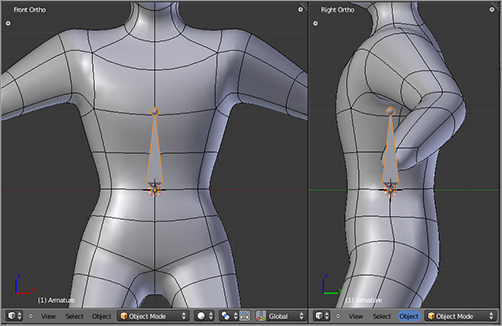
Rotating the bone
Placing the bone at the base of the torso
Extrude the first child of the bone by pressing the E key followed by the Z key to pull the extruded bone directly upward along the z axis, as shown in . Do this again three more times to create bones for the chest, neck, and head, as shown in .
Extruding a new bone
Extruding bones for the chest, neck, and head
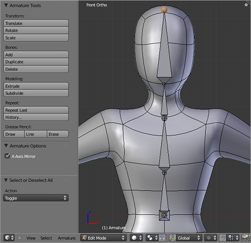
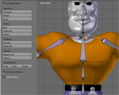
Next, you will extrude bones for the shoulders. However, to do this, you will use X-Axis Mirror so that you will not need to duplicate your efforts. Turn on X-Axis Mirror by clicking the check box in the Tool Shelf to the left of the 3D viewport (the Tool Shelf is accessed either by pressing the T key with the mouse over the 3D viewport or by clicking the little plus sign in the upper left of the 3D viewport), as shown in .
HOTKEY: Pressing T over the 3D viewport accesses the Tool Shelf.
Activating X-Axis Mirror
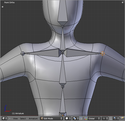
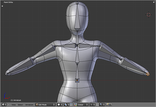
When you have activated X-Axis Mirror, select the joint at the base of the neck by right-clicking the bone node there. Do a mirrored fork extrude by pressing Shift+E to extrude the shoulders, as shown in . Use the plain E key to extrude two more times to form the rest of the arms, as shown in . Because the shoulders were fork-extruded with Shift+E and X-Axis mirror is active, edits you make on the arms will be automatically mirrored.
HOTKEY: Pressing Shift+E performs a forked extrude on armatures in Edit mode when X-Axis Mirror is active.
Mirror-extruding the shoulders with Shift+E
Extruding the arms
You’ve finished with the top half of the body. Now select the tip of the root bone (the first bone you added), and mirror-extrude downward with Shift+E to make the hips. From there, extrude two more times downward to make the bones of the legs, as shown in .
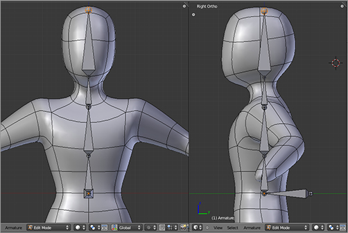
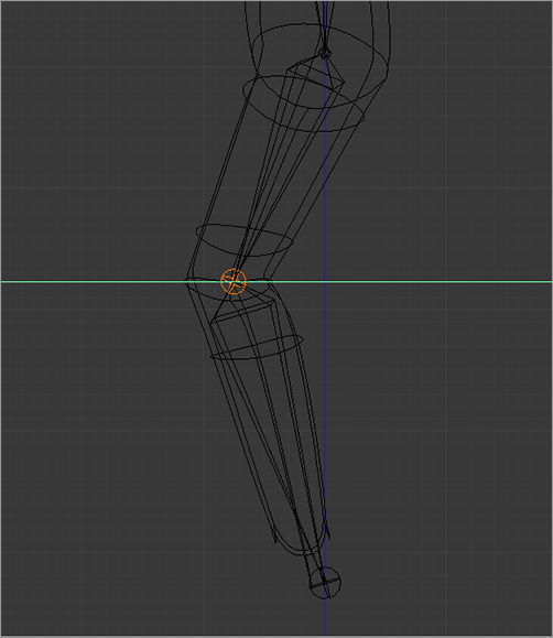
Enter side view by pressing 3 on the number pad. Select the knee joints, grab them with the G key, and move them forward along the y-axis, as shown in , so that they are slightly bent and conform to the shape of the mesh. Do the same with the elbows.
It helps to have arms and legs bent slightly in their rest position to facilitate proper bending during IK posing. You should bear this in mind when modeling your mesh and when setting up your armature.
Extruding the leg bones
Bending the legs slightly at the joints
Inverse Kinematics
There are two main ways to pose characters, forward kinematics (FK) and inverse kinematics (IK). These will be discussed in more detail in later chapters, but it’s important to have an idea of the difference. FK is the simplest way to pose a character. It is analogous to the way you would usually pose a jointed doll. When you rotate the upper arm of a doll, the forearm and hand follow that motion. IK posing is done by moving the tip of a chain of bones. The computer automatically calculates the rotation of the other bones in the chain appropriately.
As you’ll see later in this book, FK posing is good for animating graceful arcs, and for this reason it is appropriate for free-swinging limbs. IK posing is best suited for cases when the endpoint of a limb (for example, the hand or foot) is fixed in place or moved by an external force. A classic example is walking, in which each foot is fixed on the ground while the rest of the body moves. When you try to animate a character walking by using only freely rotating legs, you get the appearance of sliding feet. For this reason, IK posing is often used for feet. A fully functional, flexible rig for general-purpose character animation requires that all limbs be poseable in either IK or FK. You’ll see how this is done in the next section of this chapter, when you work with the Captain Blender armature.
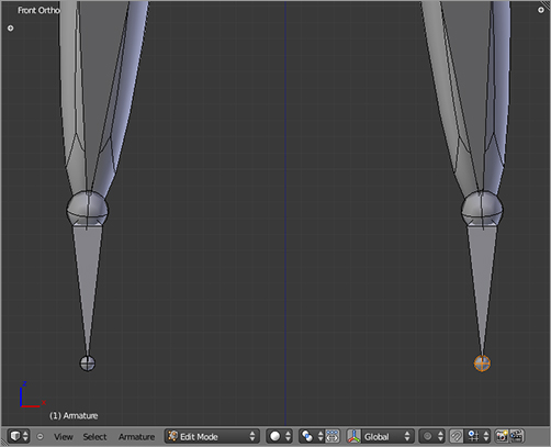
To enable IK posing for the legs in this simple example rig, you need to add IK bone constraints on the lower leg bones. However, before doing this, you need to add function bones to act as the constraints’ targets. Create these bones by extruding once more downward from the tips of the legs. These bones will extend beyond the edge of the mesh, as shown in .
Extruding function bones to act as IK targets
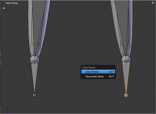
These bones will be used to control the movement of the leg, so they must be independent of the leg. Select one of the bones (be sure the whole bone is selected, not just the tip or the root), press Alt+P, and choose Clear Parent to remove the parent-child relationship between the bones, as shown in . This also disconnects the bones so that the tip bones can be moved freely of the legs.
HOTKEY: Pressing Alt+P brings up a menu to clear parent relationships between objects or bones.
Bone constraints are dealt with in Pose mode. So far, you’ve seen the armature in Edit mode, which is analogous to Edit mode for meshes, and Object mode, which is identical to Object mode for other 3D objects. Armatures also have another mode that can be used: Pose mode. As the name suggests, Pose mode is the mode in which the completed armature is posed. You can rotate and move bones in a way analogous to the way you would control a doll or puppet, subject to whatever bone constraints you have in place. You can’t add new bones or change the way the bones are connected to each other like you can in Edit mode.
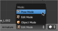
To create the IK constraint, enter Pose mode using the drop-down menu in the 3D viewport header, as shown in , or by pressing Ctrl+Tab.
Removing the parent-child relationship with Alt+P
HOTKEY: Pressing Ctrl+Tab toggles between Pose mode and Object mode when an armature is selected.
Entering Pose mode
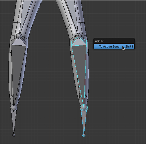
In Pose mode, select the target bone first and then hold Shift and select the shin bone of the left leg. The order of selection is important to ensure that the constraint is applied to the correct bone. Press Shift+I, and choose To Active Bone to add the IK constraint, as shown in .
HOTKEY: Pressing Shift+I adds an IK constraint to the active (last selected) bone targeted to the previously selected bone in Pose mode.
Adding an IK constraint
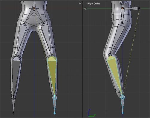
When you’ve done this, the shin bone should be displayed in yellow, and a dotted line should extend from the tip of the IK chain to the base of the root bone, as shown in .
The IK constraint displayed
You can adjust the parameters of this constraint directly in the Bone Constraints panel of the Properties window, as shown in . Set the Chain Length value to 2, as shown in that figure. This ensures that IK posing is calculated only for the bones of the leg up to the hip. You don’t need to worry about the number of the bone in the Bone field as long as the constraint is on the shin bone. The important thing in this figure is the chain length value.
Adjusting the parameters of the IK constraint
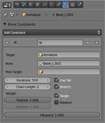
The default chain length is defined as 0, which actually means that the entire chain of bones, up to the root, is included in the IK chain. This is often not what you want and can lead to strange behavior of the armature when you pose the IK solver. Be sure to set your Chain Length value to end at the point where you want your IK chain to stop.
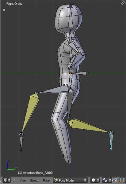
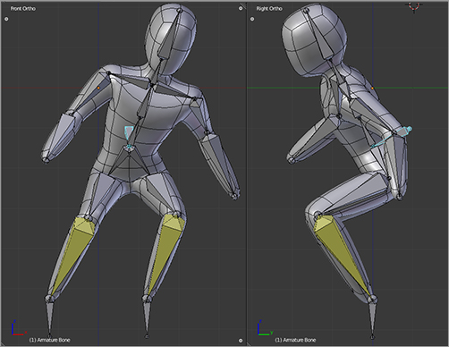
And with this, the IK constraint is in place on the left leg. Follow the same steps to add an IK constraint to the right leg. To pose the legs, move the IK target bones and observe the effect, illustrated in . If you want to return the armature to its rest position, select the bones that have been moved, and press Alt+G. If you’ve posed bones in the upper body by rotating them, return them to the rest pose by pressing Alt+R.
Posing the legs with IK
Skinning
The armature can now be posed, but it doesn’t affect the mesh. To make it affect the mesh, you need to skin the rig, that is, assign bone influence to each vertex of the mesh. This influence is represented by vertex groups for each bone. Each vertex group contains weights ranging from 0 to 1 for every vertex that is a member of the group. If a vertex has a weight of 1 for a particular bone, then the bone’s movement will have the maximum influence on the location of the vertex.
This may sound a little complicated, but fortunately there are a lot of tools for working with these weights and even setting them automatically.
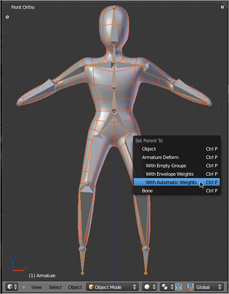
In this example, you’ll use the automatic weighting functionality. To skin the rig, enter Object mode, select the Mesh object, and then hold Shift and right-click to select the Armature object (as usual, the order you select these objects is important). Press Ctrl+P to set up a parent relationship. Choose Armature Deform With Automatic Weights, as shown in , and presto—you’re done! That wasn’t so painful, was it? Try posing the armature now in Pose mode. The mesh should deform as shown in .
The IK constraint displayed
The rigged mesh
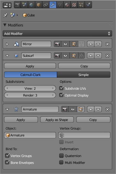
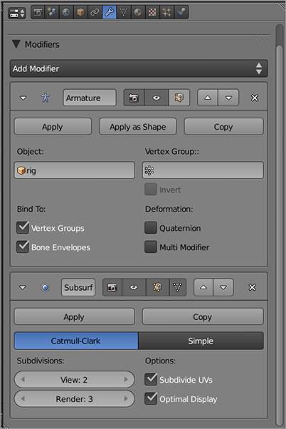
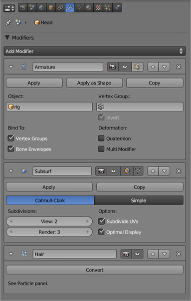
Actually, there’s still one more simple thing to do to make the deformation as nice as possible. Take a look at the Modifiers panel in the Properties window, as shown in . You’ll see some familiar modifiers; there’s the Mirror modifier used in modeling the mesh, the Subsurf modifier used to smooth the mesh, and now, at the bottom of the modifier stack, the Armature modifier, which as you can guess deforms the mesh according to the armature pose. However, recall the discussion about modifier order in Chapter 2. It would make more sense to have the armature deformation calculated before the resulting mesh was smoothed using the Subsurf modifier. To make this happen, simply move the Armature modifier up one position by clicking the up arrow icon in the upper right of the Armature modifier’s widget. As you can see in , you get considerably nicer deformations.
The Modifier stack
Improving deformations by correcting modifier stack order
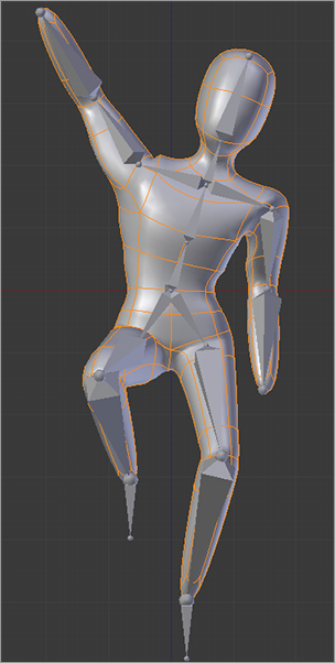
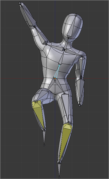
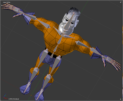
You can now pose your model freely, as shown in . Experiment with this rig, and note the difference between how the IK posing of the legs and the FK posing of the rest of the limbs works.
Posing the finished rig
. I recommend you spend a little time browsing this panel and seeing what kinds of things are available. For example, there are add-ons for the Add Mesh functionality that enable you to expand the variety of mesh primitives you can add to a scene and add-ons to enable you to use a variety of measuring systems.
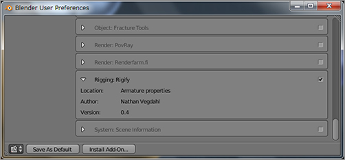
The add-on you want right now is Nathan Vegdahl’s Rigify add-on, which you’ll find by scrolling down and looking for the Rigging: Rigify entry, as shown in . Click the check box to the right of that add-on, and click the Install Add-On button. Now you’re ready to rigify.
The Add-Ons panel
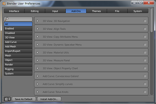
Installing the Rigify add-on
Creating a Meta-rig
The first step in making the Captain Blender rig is to add a meta-rig armature. The reason this armature is referred to as a meta-rig is that although it is an ordinary armature object, you will not be using it as your actual rig. Rather, you will use this armature to create a guide or template to tell the Rigify algorithm how to create the actual rig that you will use to pose your character. The meta-rig will represent the locations of the joints and the rotations of the bones appropriate to the individual character you are rigging. Once you set up the meta-rig, the rigging itself will be almost completely automatic.
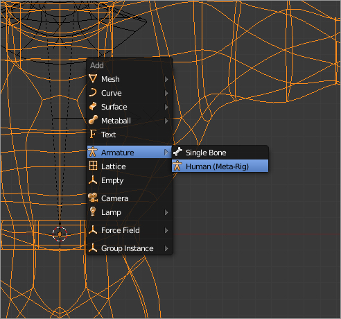
In Object mode, you’ll add an armature just as you did in the previous example. However, this time, you won’t just add a single bone. Instead, you’ll select Human (Meta-Rig) from the menu, as shown in . Press Alt+G to make sure the object is centered in the 3D space.
Adding a meta-rig
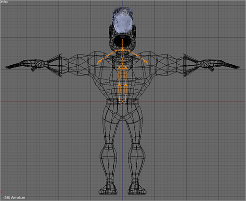
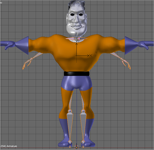
Assuming that your model is the same as the one described so far in this book, the resulting armature will look something like what you see in . Clearly, the scale of the armature and the scale of the Mesh objects do not match, so they will need to be changed.
The armature and meshes do not match in scale.
In this case, you’ll resize the meshes. Select the body mesh in Object mode, and then press Shift+G to bring up the Select Grouped menu; choose Type as shown in in order to select all the meshes in the scene. This will select the head, mouth, and eyes objects in addition to the body object. Scale them down so that the size of the character mesh is roughly the same as the size of the armature, as shown in .
Selecting all the meshes in the scene with Select Grouped
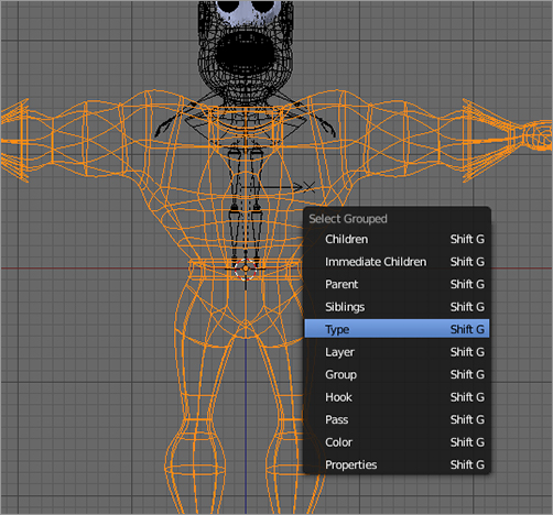
HOTKEY: Pressing Shift+G brings up the Select Grouped menu to enable you to select all objects with shared characteristics, such as all objects that belong to a group or all objects that share a type.
After you’ve scaled the meshes, you should apply the new scale. This sets the current size of the object as the unaltered scale of the object. For the body, eyes, and mouth, do this by simply selecting the object, pressing Ctrl+A, and choosing Apply Scale.
In the case of the head, it’s not quite so simple because applying the scale here changes parameters for the hair particles in complicated ways. If you apply the scale on the head, your hair particles may behave in unexpected ways.
Scaling the meshes to match the armature
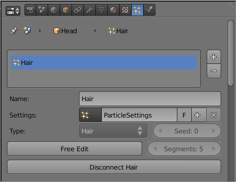
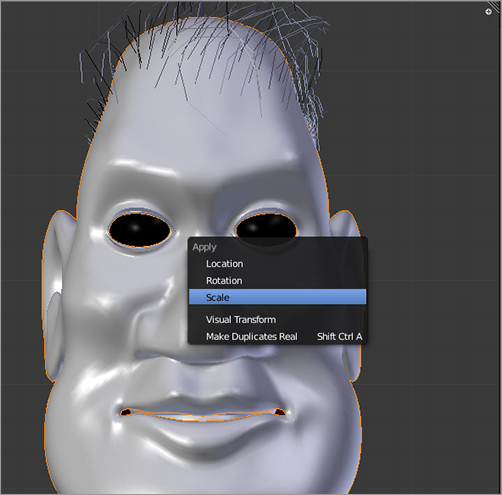
The way to apply a new scale to an object with hair particles is to disconnect the hair first, then apply the scale, and then reconnect the hair. To disconnect the hair, click the Disconnect Hair button on the Particles panel for the hair particle system, as shown in . Then apply the scale to the head object with Ctrl+A, as shown in . Finally, return to the Particles panel, and click Connect Hair.
Disconnecting the hair particles
Applying the scale of the head object
In some cases, you may find that the mesh jumps some distance from where it was previously when you do this. This is a trivial bug in the version of the software I’m working with right now. If this happens, simply select all the vertices of the mesh in Edit mode with the A key, and move the entire mesh to its original placement.
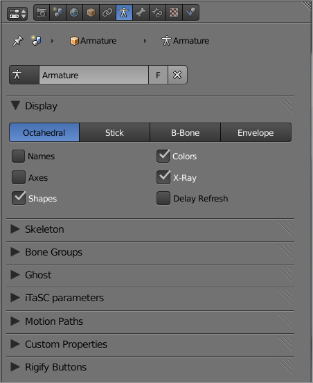
Once you’ve finished scaling the mesh, you can return to setting up your meta-rig. In the Armature properties panel under Display, select the X-Ray box as shown in so that your armature will be displayed through the mesh. This makes it much easier to see what you are doing when editing the armature. Also, turn on X-Axis Mirror in the Tool Shelf, as shown in , so that you can edit only one side of the armature and the other side will automatically mirror the changes.
Next, in Edit mode, edit the armature to match the mesh. You’ll have to do this on your own by selecting bones and joints and moving, rotating, and scaling them as necessary. Try to do as much as you can by selecting groups of bones together, for example selecting the whole hand with Box Select (B key). Stick to the front, side, and top orthogonal views and constrain your transformations to the x-, y-, or z-axis when you can. The important thing is to get the joints in the right places for your mesh and make sure that the bones are all where they ought to be and rotated correctly. Think of the armature as your character’s skeleton, and place the bones appropriately to wind up with something along the lines of the armature shown in .
Setting the X-Ray display option
Turning on X-Axis Mirror
Bone placement for the Captain Blender meta-rig
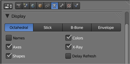
Once you’ve placed the bones and joints in the correct locations, it’s time to look a little closer at some crucial bone rotations. In particular, the roll of the bone—the rotation around the bone’s local y-axis (lengthwise)—determines how the bone will bend at joints. To adjust the roll properly, you will want to set the armature Display settings to display bone axes, as shown in . When you set this, each bone will show a representation of the directions of its three axes.
Displaying bone axes
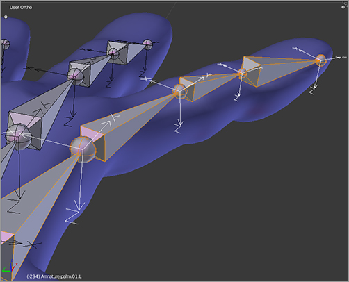
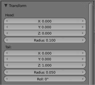
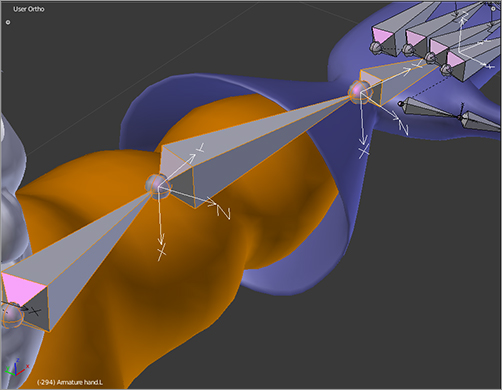
Rigify will generate a rig with joints that rotate around the x-axis of bones where relevant, with the joint’s “inside” rotation being in the direction of the drawn z-axis in the bone axes representation. shows an example of how the bones’ roll should look in the case of fingers. Note that the joints of the fingers will now naturally bend around the x-axes of the bones and with the inner angle in the direction of the positive z-axis, as shown in the display. Adjust the bone roll value directly in the Roll field of the Transform Properties shelf, as shown in . You can access the Transform Properties shelf by pressing the N key in the 3D viewport (or by clicking the small plus sign in the upper-right corner of the 3D viewport).
Bone roll angles for the fingers
Transform properties
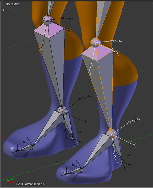
Other important places to get your bone rolls right are at the elbows and wrists, shown in , and the knees, shown in . If the bone rolls are off, you’ll find that the final rig’s joints will bend wrong. Don’t worry too much about getting this perfect, though. You can always delete a generated rig, adjust the rolls, and generate again after testing.
Bone rolls for elbows and wrists
Bone rolls for legs
Generating the Rig with Rigify
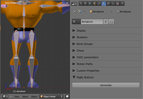
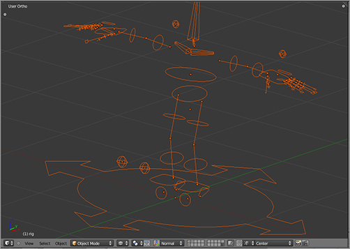
Once you have the meta-rig set up, the next step is to use it as the basis for a full rig. To do this, select the meta-rig armature object, and find the Rigify Buttons settings in the Armature properties window, as shown in . Click Generate. Your rig will appear as shown in . The rig is a new armature object with the object name rig. The original meta-rig armature is no longer needed. You can put it on a different layer out of sight. It’s best not to delete it, though, because you might want to go back and use it to regenerate a new rig.
Rigify buttons
The generated rig
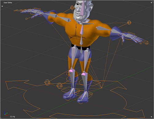
This new rig object has saved you a ton of work. As you’ll soon see, it is already fully poseable and ready to skin, with IK/FK switching functionality and a load of other features that make it an incredibly flexible and easy-to-use character rig. However, there are still a few adjustments you should make to ensure that the rig is best suited to your model.
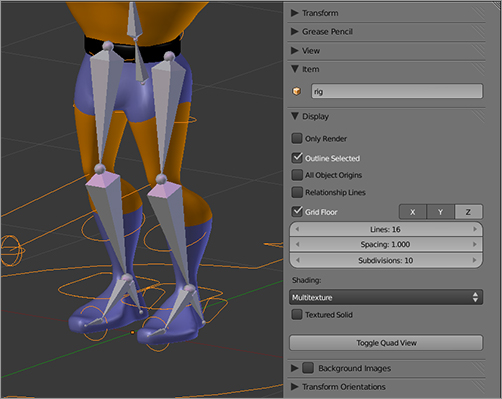
First, take a look at the display options on the Properties shelf shown in . I find that it’s not really necessary to constantly see the dotted lines indicating parent relationships, so I deselect Relationship Lines in the Display options. This is a personal preference, but it helps to clean up the viewport a bit.
Clearing relationship lines from the display
Next, you should make some adjustments to the custom bone shapes used for the control bones. As you learned at the beginning of this chapter, there are control bones, deform bones, and function bones in a rig. When you generate a rig, only the control bones are visible, and they have been set to display using specialized mesh shapes. The leg control bones, for example, display as blue rings around (or in this case penetrating) the legs, as shown in . It’s a good idea to edit these mesh shapes in a way that makes them more accessible when posing.
Circular custom bone shapes for leg control bones
You’ll find the mesh shapes for the custom bones all collected together on layer 20, as shown in . Select them all by pressing the A key, and suddenly you’ll see them pop into position showing their actual placement in the rig, as shown in .
Mesh shapes for custom bones
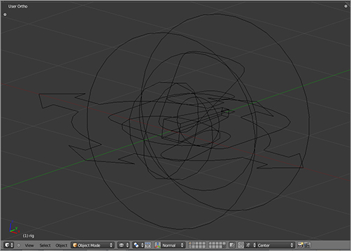
Custom bone shapes correctly placed
Make this layer and the layer your character model is on both visible. You can now select the custom bone Mesh objects in the ordinary way and tab into Edit mode to edit them, as shown in . You’ll need to scale some of the rings and control shapes and move them around a little bit to create a set of controls that visually suits your character. The upper arm control bone, for example, was entirely hidden by the mesh before I edited the control bone mesh. The resulting control armature should appear something like the one shown in . Note that the armature is not displayed in X-Ray style. This helps to enhance the three-dimensionality of the control bones and make them more intuitive to use.
Custom bone Mesh objects
Control bones for Captain Blender
Attaching the Mesh
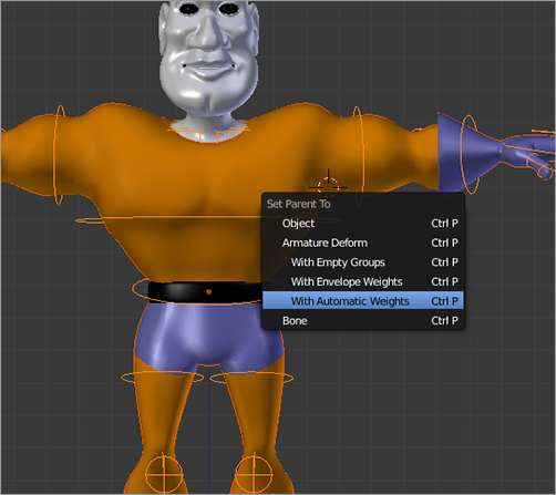
Your body armature rig is now finished. Next you need to associate the armature with the rig. This entails two tasks: creating an Armature modifier and creating a set of vertex groups representing the influence of each bone. As you saw previously in this chapter, both of these steps are handled automatically by Blender when you parent the mesh to the armature using automatic bone weights. You’ll do that now. First enter Object mode. Then select the mesh followed by the armature (using Shift+right mouse button). Press Ctrl+P to bring up the parent menu shown in , and choose Armature Deform With Automatic Bone Weights.
Parenting the body mesh to the armature
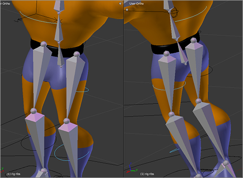
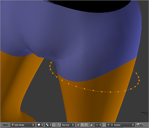
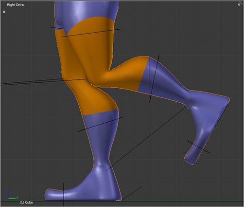
Recall the importance of the order of modifiers on the Modifier stack. Move the Armature modifier up above the Subsurf modifier on the stack, as shown in , to ensure the best deformations. You can see the effect of changing the modifier order on deforming the leg in .
Changing the order of the modifiers
Before and after rearranging the modifiers

Weight Painting
Blender’s automatic vertex weighting functionality is a great improvement over the way skinning used to be done. For simple character meshes, particularly skinny ones where the mesh stays fairly close to the bones that should control it, the automatic weighting may be all that’s necessary. For most characters, however, you must adjust the weights by hand to get optimal effects.
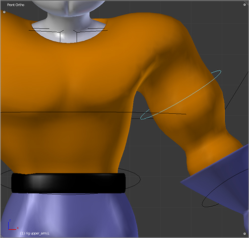
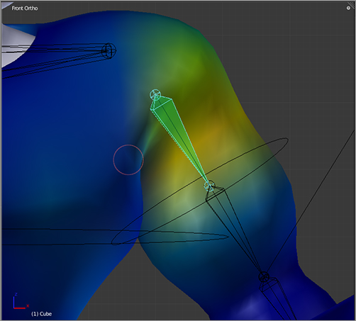
Captain Blender’s broad chest is an example of a place where the automatic weighting is likely to need some help. To see why, enter Pose mode, grab one of Captain Blender’s bicep control bones, and rotate it downward, as shown in . Notice that as you do this, the side of Captain Blender’s torso is pushed inward with the motion of the arm. The arm deform bone is influencing the vertices of the body in a way that it shouldn’t.
Incorrectly set weights
The solution to this is to manually set the weights (influence) of the bones on the vertices. This can be done in several ways, but the most intuitive and visual way to do it is to use weight painting.
Weight painting is a way to make bone influences visible and to edit them directly, similar to spray-painting. Blender’s Weight Paint mode enables you to select deform bones to display their influences as colors on the surface of the mesh.
To do this, however, you need to make the rig’s deform bones visible. So far, you have only seen the control bones of the mesh. The deform bones have been placed on a hidden bone layer. Bone layers are analogous to the view layers you’ve worked with in the 3D viewport. However, rather than controlling the visibility of objects in the 3D scene, bone layers control the visibility of bones in an armature. Each bone can be placed on a layer in the Bone properties window, and the armature’s bone layer display is set on the Armature properties window.
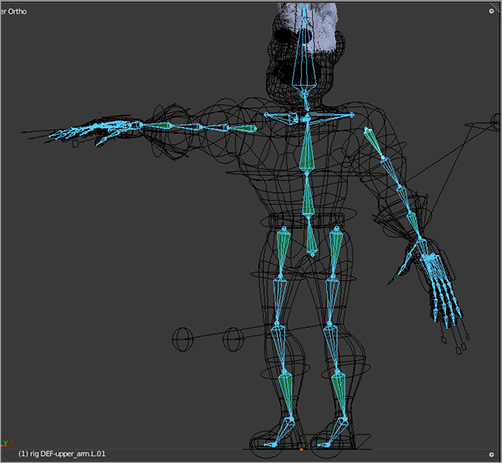
In the rig you’ve just created, the deform bones are all located in the third layer from the right on the bottom row, shown highlighted in . The top row layers contain the various control bones. Select layers to make visible by pressing Shift and clicking the layer’s button. For weight painting, you will want the deform bones layer visible. You’ll also want the control bones visible and set to X-Ray draw mode so that you can easily pose the rig during the process of weight painting.
Selecting the bone layer with the deform bones
The deform bones are shown selected in . These are the bones that actually directly affect the deformation of the mesh. As you can see, the deform bones make up a shape that is structurally pretty similar to a human skeleton. These are the only bones you need to worry about for weight painting.
Deform bones selected
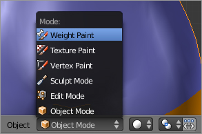
To enter Weight Paint mode, begin with the armature in Pose mode, and then right-click the mesh to select it. This part is important. If the armature is not in Pose mode before the mesh is selected, the bones will not be individually selectable in Weight Paint mode. When you select the mesh, the mode will automatically switch to Object mode. From there, you can enter Weight Paint mode using the menu in the 3D viewport header, as shown in . If you did this correctly as described, the mesh will be displayed with weight paint, the armature will be displayed in Pose mode, and you can select and pose its bones. The mesh will mostly appear deep blue. Depending on which bone was selected last when you entered Weight Paint mode, there may be areas of other color on the mesh.
Entering Weight Paint mode
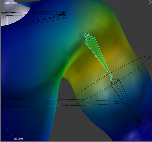
Weight paint is a visual representation of the weights of vertex groups on vertices. By default, the color range goes from blue (weight value 0.0) to yellow (weight value 0.5) to red (weight value 1.0). Here the term weight is used interchangeably with the term influence. For each bone, the corresponding distribution of colors over the surface of the mesh shows you where that bone does and doesn’t have influence.
Selecting control bones will not show any vertex influence. This is because nondeform bones do not influence the mesh directly. Select the deform bone for the upper bicep, as shown in . You can see that the main influence of that bone is where it belongs, on the upper part of the bone. However, if you look close, you will see a yellowish or greenish tint extending well up onto the torso and chest. There is also too much yellow around the underarm. These are the problem areas. In the grayscale representation of this book, the yellow appears as lighter gray, and the blue appears as darker gray.
Weights for the upper-arm deform bone
The settings for weight painting are accessible through the Tool Shelf in the 3D viewport (you can open the Tool Shelf with the T key), as shown in .
Weight paint settings
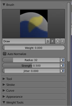
You can choose brush types by clicking the brush type icon and choosing the radius, strength, and jitter of the brush in the correspondingly named fields. The Weight field determines the weight (the weight paint color) that you’ll be painting. The Strength value determines how strongly the new color overrides the current color. You can think of it something like opacity in traditional digital painting environments. For reducing the weight on the torso, you should set Weight to 0.0 and Strength to something like 0.5, as shown in the figure.
You now begin the task of weight painting. As you paint 0 weight influence onto the mesh, you will see the mesh’s deformation change in real time. The chest and torso will return to its undeformed state as the vertex weights are diminished. Eventually, after painting the chest, torso, and underarm, you’ll arrive at a deformation that looks something like .
Weight painting the shoulder, chest, and underarm
Re-pose the arm a few times to see how the deformation looks in different poses. Also, keep in mind that the upper bicep may not be the only bone causing problematic deformations. The lower bicep bone may also be influencing the torso. Continue weight painting until all the deform bones in the model influence only the parts of the mesh that they should influence and all deformations are as smooth as you can get them.
Be sure to experiment with fairly extreme poses. Of course, there is a limit to the range of poses you will use in actual animation, but the character should deform nicely in all of the possible poses, so make sure you go through a full range of motion. In , the hand is posed at a sharp angle to emphasize the problems with the glove flare. The glove and arm need to be weight painted to fix this.
In , you can see the effect of painting zero weights onto the glove flare with the hand posed downward. In , you can see that posing the hand upward reveals other problems. These can also be solved by painting zero weights on the arm mesh.
Problems with the glove weights
Weight painting the glove flare
Weight painting the arm mesh
You can also set your weight paint options to do additive, subtractive, or multiplicative painting and also to restrict the painting to lighten and darken (light meaning higher or redder values; dark meaning lower or bluer values). There are circumstances in which these finer controls come in handy, but I do not think you need them for this model.
Effective weight painting requires patience and some skill, and experience and practice benefit you more than reading about it, but here are a few pointers you should keep in mind:
- Paint for posing. The whole reason for weight painting is to make sure your meshes deform nicely when posed, so you should pose your model frequently while weight painting, as you saw in the earlier figures. Areas that deform in unwanted ways will be easy to identify.
- Work with vertex groups directly when you can. There are often cases in which many more vertices belong to a particular vertex group than are necessary. An advantage of weight painting—that it lets you apply subtle weight changes to verts—is also a disadvantage because you can inadvertently give verts hard-to-see, near-zero weights that can add up and become problematic. For this reason, it is a good idea to occasionally go into Edit mode with a bone selected and select the vertex group for that bone in the Vertex Groups area of the Mesh Properties window.
- Be conscious of the possibility of overshooting. If you are painting the pinky red and you are not careful of the position of your mesh, you might inadvertently hit points on other parts of the mesh. You might wind up making the heel green, for example, which would result in messy deformations of the foot every time the hand moves. There are some useful tricks for avoiding this. In Weight Paint mode, you can click the icon to the right of the display mode drop-down menu in the header to enter Face Selection mode and select the faces that you want to paint.
 When you return to Weight Paint mode, only the selected faces receive the weight paint. You can hide faces with the H key in Face Selection mode, and they will remain hidden in Weight Paint mode, enabling you to weight paint hard-to-reach areas.
 - Be aware of the effects of unwanted bone influence. If an area of mesh is fully red but it does not seem to be following the bone it is supposed to follow, it is probably also being influenced by another bone that is not moving. Posing the armature in a drastic way might help identify the direction that the unwanted deformation is pushing your mesh and can help narrow down where the offending bone is.
- Make sure your bones are deform bones. This should be obvious, but nondeform bones can have nonzero weights, even if they don’t do anything with those weights. You might think you’re painting a bone’s influence, but if the deform button is not selected for that bone in the Bone properties, it doesn’t move the mesh anywhere. If your mesh is not responding properly to a bone, even if it is properly weighted, this might be the problem.
Several Python scripts in the standard distribution of Blender can help clean up vertex weights and reduce problem areas. You can read more about how to use these scripts in Chapter 12.
Finishing Off
The head object needs to be armature-parented to the armature in the same way that the body was. Once again, you need to make sure the modifiers are in the correct order. In the case of the head, there’s one more modifier to worry about: the Hair particle system. Particles are also dealt with in the modifier stack. If the Hair particle modifier occurs above the Armature modifier in the stack, then deforming the mesh with the modifier will leave the hair in place. Clearly, the hair should follow the position and shape of the head, so be sure that the order of the modifiers is Armature first, then Subsurf, and then Hair, as shown in .
The modifier stack for the head
For the other objects in the head, the mouth and eyeballs, you won’t use the Armature modifier right now. These will be rigged using different bones in the next chapter. For a quick, temporary way to make them simply follow the head bone, you can use bone parenting.
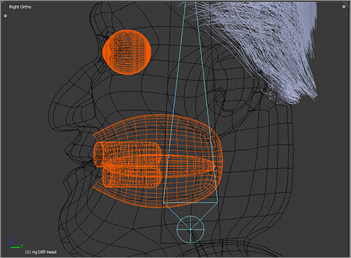
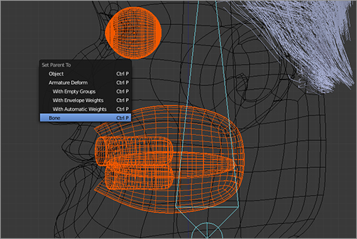
Begin with the armature in pose mode, and then select the objects you want to bone-parent (the eyeballs and mouth mesh). Shift+select the armature, which will be in Pose mode with individual bones selected. In the armature, select the head bone. You should wind up with the Mesh objects selected and the head bone selected in Pose mode, as shown in . Press Ctrl+P to bring up the parent menu, as shown in . Select the Bone option from this menu. If Bone is not listed, go back through this paragraph, and make sure you’ve selected everything in the correct order and mode. Bone parenting is very useful for mechanical rigging and other rigging where you want to control the movement of objects without needing to deform their meshes. In this case, it gives you a quick and dirty way to make the eyes and mouth follow the motion of the head until you can get around to rigging them properly.
Preparing to bone-parent objects
Bone parenting
Posing
You’ll get into the details of posing later, when you start into the character animation chapters of this book. For the time being, it’s enough to know some basics so you can start to play around with your rig.
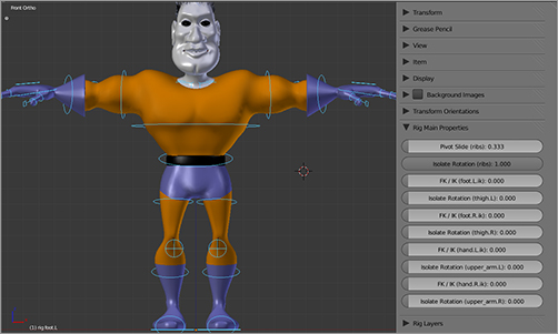
By default, this rig’s IK constraints are set to zero influence, so the posing is FK. You’ve seen already how to do FK posing by grabbing bones in the limbs and rotating them. To do IK posing, you need to turn on IK influence for the limbs. This is done in the Rig Main Properties panel in the Properties shelf (N key) in the 3D viewport, as shown in . Notice that there are four FK/IK fields. The values in these fields determine whether FK or IK posing dominates. If the value is 0.0, the posing is FK; if it is 1.0, then posing will be IK. Values in between will result in both FK and IK controls having an influence, so the influence can be smoothly graduated.
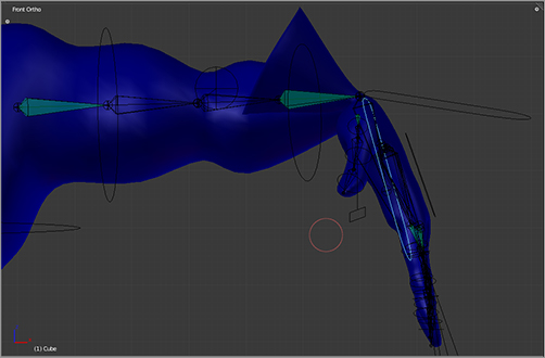
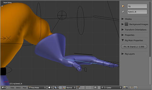
To pose the left arm using IK posing, select the hand.L.ik control bone, and ensure that its FK/IK property is set to 1.0 under Rig Main Properties, as shown in . Pose the arm by moving the hand.L.ik bone as shown. Note also that if you change the FK/IK value now, the arm will smoothly return to its original FK pose.
IK/FK switching controls
IK posing the arm
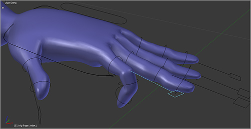
One more clever posing trick in this rig is the use of bone drivers for finger curl controls. You’ll learn more about drivers in the next chapter, but their use here is some fairly advanced rigging. Fortunately, it’s all done automatically for you, so you just get the benefit of very easy-to-control fingers. shows the finger curl controls. Scaling the finger curl control bone down (S key) will curl the finger, and scaling it up will bend the finger backward.
Curling the finger by scaling down the finger control bone
As you’ve seen, different control bones work differently. Some controls are rotated, some are grabbed (moved), and some are scaled. When you want to return the armature to its unposed state, you need to be sure to use Alt+R, Alt+G, and Alt+S as appropriate to remove rotation, translation, or scaling.
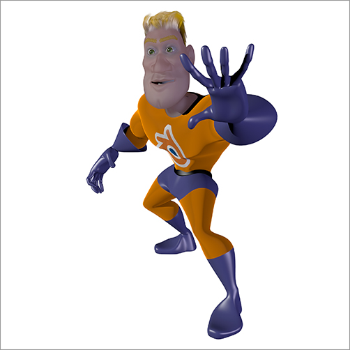
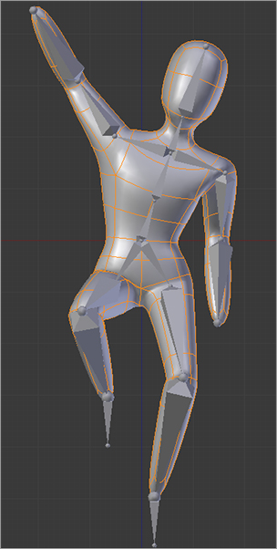
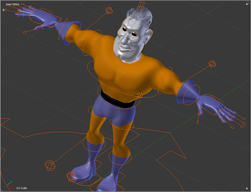
At this point, you’re ready to start playing around with posing. In , you can see that our hero has begun to come alive! You’ll deal with the spaced-out expression on his face in the next chapter when you work on facial rigging. You’ll also see how to fix other problem areas of the mesh that are hard to get right using weight painting only, such as the belt.
I’ve been rigified!