Chapter 3
Completing the Model with Materials, Textures, and Hair
Previous chapters covered the basics of using Blender’s various modeling tools to build organic shapes. But this is only the first step of creating characters. By default, all the shapes you build begin as a uniform, dull gray, slightly glossy material. To make characters interesting and lifelike, or even just to change their color, you need to delve into the world of materials, textures, and particle hair to complete the model.
- Materials and Material Slots
- Material Properties
- Textures and UV Mapping
- Working with Particle Hair
shows a possible arrangement of slots and materials. In this figure, four slots are shown represented by rectangles on the left, and three materials are shown, represented by circles on the right. Slots 3 and 4 both link to the third material, labeled M3. In practice, this means that if you edit M3 by changing its color or other properties, the parts of the mesh with slots 3 and 4 assigned will change.
Materials and material slots
In fact, slots in Blender are not explicitly numbered. Past Blender versions used explicitly numbered material indices, but now there is simply a stack of slots. The numbered labels I use in the figures here are simply counting from the top.
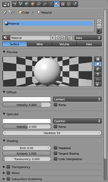
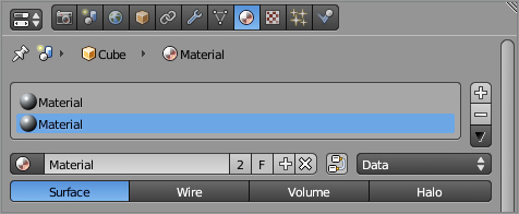
To take a look at material slots directly, fire up Blender, and select the default cube. Look at the Material Properties window, as shown in . The material slots for this object are shown in the panel near the top of the window with the plus and minus icons to the right of it. By default, the cube is associated with a single material slot containing a material with the name Material. Conceptually, what you’re seeing represents the slot/material relationship shown in .
The Materials Properties window
The default material arrangement
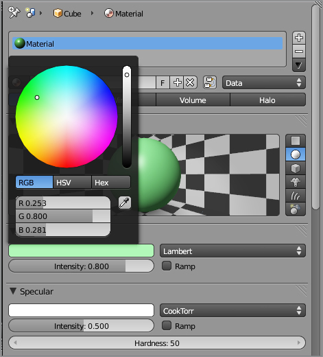
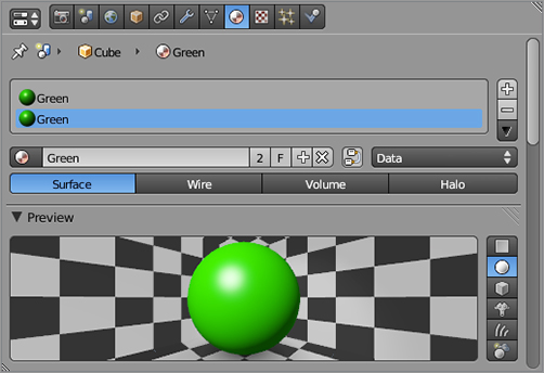
Click the Diffuse color field to bring up a circular color picker, and set the diffuse color of the material in this slot, as shown in . I’ve set this material to green.
Changing the diffuse color
To have more than one material on a mesh, you need to first add a new material slot to hold the new material. You do this by clicking the + sign to the right of the material slots stack. When you do this, a new slot will appear, as shown in . This material slot is also labeled Material. This means that the new material slot is associated with the same material as the first slot. Conceptually, the arrangement is as shown in . There is still only one material to work with. Rename the Material something meaningful, like Green, by entering the new name in the material field just below the stack panel. As you can see in , the name in both slots changes to Green.
Look again at the field where you entered the name. To the right of the material’s name in this field is the number 2, the letter F, a plus symbol, and an X symbol. The 2 means that this material is associated with two users. In this case, this means that the material is being used by two slots. The F button toggles a fake user for the material. This is useful if you have a material with no slots using it that you would like to save. The plus symbol creates a new material, and the X symbol deletes the material from this slot.
Adding a new material slot
The new slot sharing a material
The material renamed
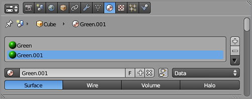
As you can probably guess by now, you want to click the plus symbol to create a new material in this slot. Another way to do the same thing is to click the button with the 2 written on it, which will have the effect of making the material a “single-user” material. When you click either of these symbols, the second slot will change, as shown in . Blender has created a new, distinct material that is an exact copy of the original Green material and named it Green.001 according to Blender’s automatic naming conventions. Any time Blender needs to name an element using an already-used name, it appends a three-digit index to the name, beginning with .001 and iterating as necessary. The situation now is illustrated in .
The newly created material
The relationship between the two slots and the two materials
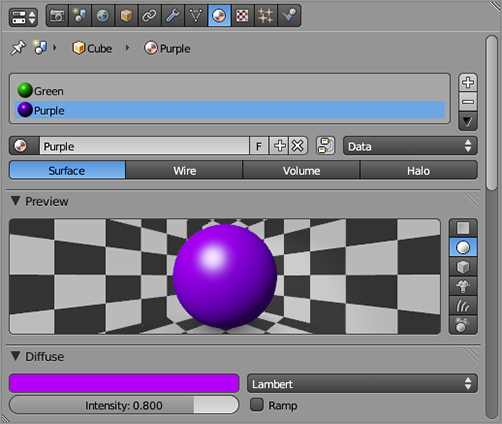
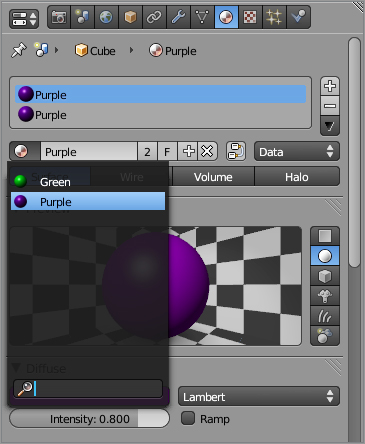
The important point here is that Green.001 is now a completely separate material. You can change this material’s properties without affecting the original Green material. Try it now by changing the color of the new material. I’ve made mine purple and renamed the material Purple, as shown in .
Green and Purple materials
If you’ve followed the steps so far, you should have two material slots on the object, with unique materials in each, one Green and the other Purple. However, the object in your 3D viewport, the default cube, is only green. This is because all the faces on the cube are still associated with the first material slot.
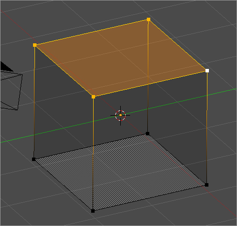
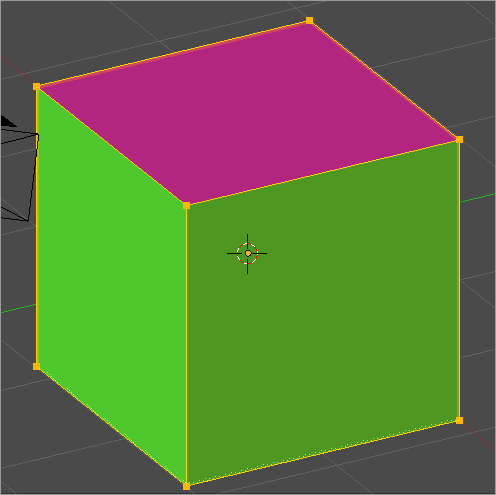
To assign a material to a face, simply tab into Edit mode, select the face or faces you want to assign the material to, and click Assign on the Material slots panel with the material slot selected. In , you can see the cube with the top face selected (the object is shown in wireframe to more clearly show the selection). With Purple selected in the material slots stack, click Assign, and the top face of the cube turns purple, as shown (in black and white, of course) in .
The cube with the top face selected
The cube with two materials assigned
You can control which materials are associated with which slots by selecting the slot and choosing a material from the material field drop-down menu, as shown in . If you choose the top slot and choose Purple from the drop-down menu, the entire cube will become purple. The top face and the rest of the cube are still associated with separate slots, but the slots both point to the same material.
Selecting which material the slot will point to
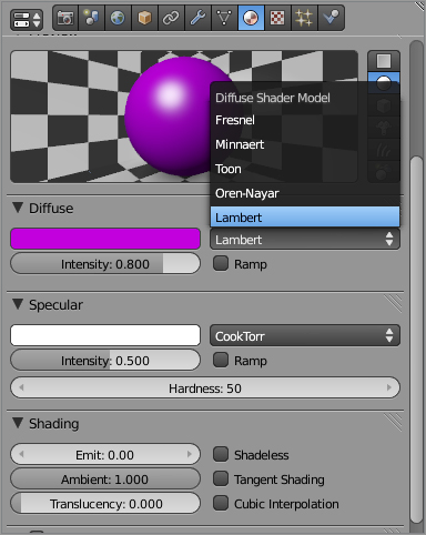
, where the drop-down menu for the diffuse shader is revealed to show the list of shader options for diffuse shading.
Shader information in the Material Properties window
Toon and Anime Style Shading
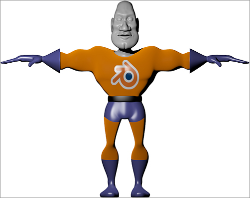
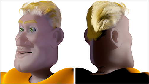
You generally use a shader to create a realistic simulation of some specific physical surface. In character animation, one common exception to this use of shaders is in toon shading, which creates a cartoon or traditional 2D anime-style appearance. Toon shaders divide gradations into several levels of shading that can be smoothed together, resulting in a sharp, cartoony distinction between lit parts and shaded parts of the object. Toon shaders are often used in conjunction with the Edge feature in the Render buttons panel, which adds an outline around the object as part of the rendering process, further enhancing the traditional 2D look.
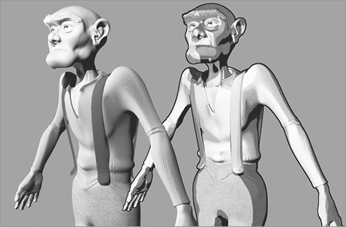
In the image shown here, the old man rendered on the right is made of toon-shaded materials with the Edge feature turned on, in contrast with the more realistically shaded and rendered old man model on the left. In this case, the materials in the old man on the right were all set to toon shading for both diffuse and specular shaders, with the Smooth value set to 0 for maximal sharpness between shaded and nonshaded areas. Specularity and size values varied between the materials, and you should experiment for the effect you want.
Material Nodes
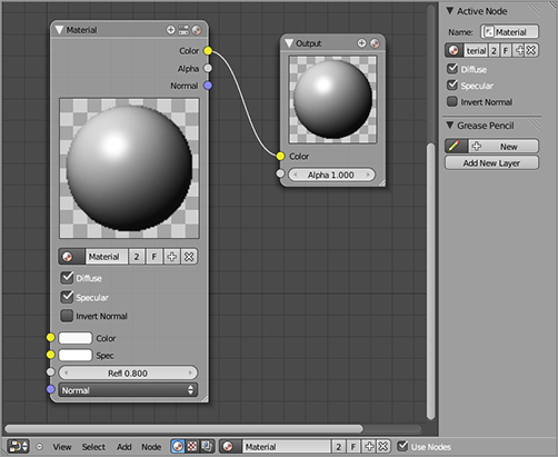
Blender has a powerful node system that you can use to create materials and to do advanced image compositing. Nodes behave similarly to the way layers behave in some 2D image-processing applications, enabling effects and inputs to be laid over one another and be combined in various ways. Nodes are much more powerful than layers in this sense because they can be combined in nonlinear ways. With material nodes, you can have complete control over every aspect of a material by combining fundamental components of materials and shaders in a flexible way. Nodes form a network of linked inputs and outputs, which you can view and edit in the Node Editor window; the basic node setup for the default material is shown here.
You will see a simple example of working with nodes in this chapter, but the knowledge you gain by working with Blender’s ordinary materials system will also not be wasted when you move on to using material nodes more heavily. Materials that use nodes are always composed of at least one basic (non-node) material that is the input to the network of nodes. The understanding you have of color, shaders, mirroring, transparency, and textures will all remain pertinent when you work with nodes. In this sense, material nodes do not replace the basic material system but rather extend it.
Shading and Materials for Captain Blender
Let’s return to the superhero model you were working on in the previous chapter. You want to now give him a colorful suit, not to mention some skin and hair.
Orange seems like a good color for Captain Blender’s tights, and blue is good for his gloves, boots, and britches. For variety, you’ll make his belt black. Click the plus symbol next to the material slots panel twice to create two new slots.
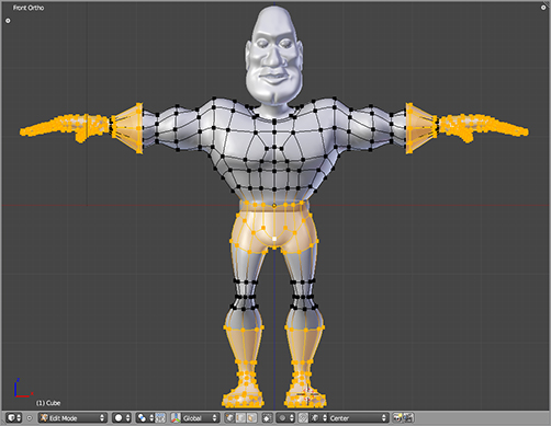
You can do the next few steps in any order. You need to associate vertex groups on the mesh with material slots, and you have to create and name a new material for each slot. By default, the entire mesh is assigned material slot1, which will be the orange material. Let’s begin by selecting the portions of the mesh you want to be blue in Edit mode, as shown in .
Selecting the parts of the mesh to make blue
Click the second material slot, and click Assign. Then click the plus symbol next to the material name field to create a new material. The new material’s name will be automatically generated to Material.001. Rename this material Blue. Rename the first material Orange.
For the Blue material, set the RGB values as R: 0.2, G: 0.2, and B: 0.6. In Blender, color values range from 0 to 1. If you are accustomed to working with a scale of 0 to 255, you should simply think of 1 as the equivalent of 255, the maximal value of the color, with 0 the same in both cases. Captain Blender’s gloves, boots, and britches are made out of super-strength PVC, and Lambert and Wardiso shaders are good for plastics, so you’ll use a Lambert diffuse shader with intensity set at 0.8; for the specular shader, you’ll use the Wardiso shader with specularity set at 0.6 and Slope set at 0.2.
For Orange, set the RGB values to 1.0, 0.3, and 0.0, respectively. Captain Blender spends a lot of time in this suit, and it needs to be easy on the skin, so you’ll give it a nice velvety surface by using a Minnaert shader with the darkness value set to 0.4. There’s very little specularity on this material, so for the specularity shader, you’ll stick with the default CookTorr shader with specularity set to 0.01.
Run a render by pressing F12 to see how these shaders are looking on your mesh. (On Mac, you will have to adjust your Mac keyboard shortcuts not to override this Blender hotkey, but you’ll be glad you did.) Check Chapter 11 for tips on how to set up your camera and lighting for a good-looking render.
Now select Captain Blender’s belt. To do this, place the mouse near one of the vertices of the belt, and press L. Because the belt is not connected by any edges to the rest of the mesh, it can be easily selected in this way. Assign the belt to the third slot, and then add a new material to this slot by pressing the plus symbol. Rename this material to Black. Set the color and shaders for the belt (you can experiment a bit with the settings).
You’ll need to do the same thing with the inside of Captain Blender’s mouth and his teeth, which are a separate object. You can select the individual mesh pieces with the L key. Keep the color dark and reflectivity low on the inside of the mouth because it will be noticeable if it is too bright.
Basic Texturing
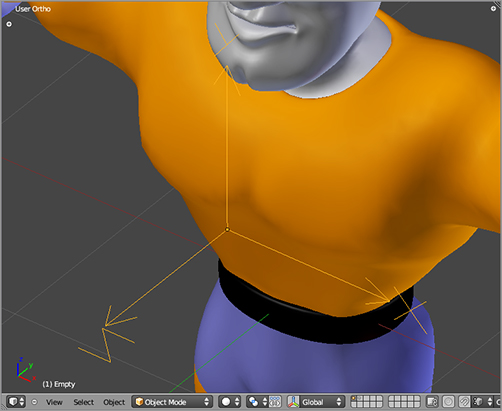
No superhero’s outfit is complete without a big splashy logo across his chest. To do this, you will use an image texture in a way analogous to a decal. To control the position, size, and rotation of the decal, you will use an Empty object. Go into Object mode, press Shift+S to snap the 3D cursor to the grid, and add an Empty object with Shift+A. Place the Empty object squarely in front of the chest by moving the empty with the G key and constraining the movement to the appropriate axes with the Y and Z keys. Rotate the Empty object by pressing the R key followed by the X key and then inputting the number 90 directly via the keyboard to rotate the Empty object 90 degrees counterclockwise around the x-axis so that the Empty object ’s z-axis points outward away from Captain Blender’s chest, as shown in .
Placing the Empty object in front of the chest
You’ll want this Empty object to follow the movement of the mesh when Captain Blender poses. To do this, you will use a special kind of parenting called vertex parenting. More specifically, you’ll use three-vertex parenting. This lets you parent an object not to another object but to actual vertices (or triples of vertices) in the second object. To do this, select the Empty object, and then hold Shift and right-click the Captain Blender mesh. Press Tab to enter Edit mode, and select three vertices around the middle of Captain Blender’s chest, near the location of the Empty object. Press Ctrl+P, and choose Make Vertex Parent. In this case, you need three vertices to make sure that the Empty object follows that of Captain Blender’s chest, even when the mesh is deformed. In cases where you only need an object’s location to be influenced by a vertex, you can use single-vertex parenting. Single-vertex parenting and three-vertex parenting are the only options for vertex parenting. If you try to vertex parent with another quantity of vertices selected, Blender will complain.
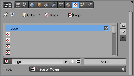
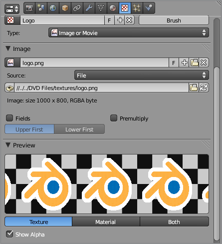
You’ll put the texture directly onto the Orange material, so make sure the appropriate material slot is active. Go to the Texture Properties window, and add a new texture if there is not one already on the material. Name the texture Logo, and choose Image or Movie as the texture type, as shown in . In the Image panel in the Texture Properties window, select the source file from your hard drive, as shown in . You’ll find the logo.tif source file in the downloadable resources directory for this book.
Adding the Logo texture
Setting the image for the texture
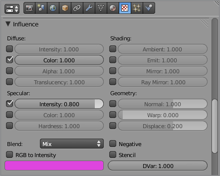
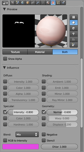
In the Influence panel, you can choose how the texture is to be used, that is, what characteristics of the texture will influence the surface appearance of the mesh. In this case, you want to use the texture’s color, so Color should be checked with the value set at the full value of 1. Also, you’ll have the texture influence the specularity of the mesh with a value of 0.8. This will make the logo on the mesh a bit shiny, like a crisp new iron-on patch. (How else do you think a superhero gets the logo on his costume?) shows the influence settings for this texture.
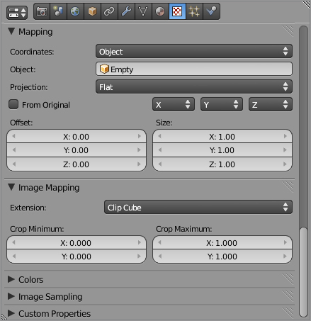
Finally, you need to set the Mapping values as shown in . Mapping settings define the relationship (mapping) of points on the texture to points on the surface of the mesh. In this case, you will be using the coordinate system of the Empty object that you just added to determine the coordinates of the texture. When the Empty object moves, rotates, or scales, the texture will do the same on the surface of the mesh. Select Object in the coordinates drop-down menu, and enter Empty in the field that appears. In the Image Mapping panel just below, select Clip Cube. This controls whether the image will be repeated or whether it will be projected through the entire mesh. With Clip Cube selected, the image will appear only once and will appear only within a cube shaped area around the Empty object. This will keep it from projecting onto the character’s back also.
Influence settings for the texture
Mapping values for the texture and image
Once you’ve made these adjustments, view the result by rendering with F12. You’ll need to make sure to place the camera so that it can see the texture and put a light in place so that you can see what it looks like. How does it look? If the logo is too large or small, you can adjust the size by scaling the Empty object. If it’s in the wrong place, you can move it around by moving the Empty object. Of course, you can also rotate the image by rotating the Empty object. shows a render of the full model with materials so far.
A render of the materials so far
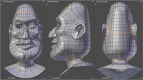
. In general, it is a good idea to try to mark the seams in places that are likely to be unobtrusive later, such as parts of the mesh that are covered by hair, are visible only from behind, or that conform to creases or concealed places in the mesh. It’s also best to try to keep your seams symmetrical on a symmetrical mesh. Finally, try to put seams in places most likely to be distorted by flattening. Real-life seams in clothing are a great reference for how seams should be created on a mesh. Think about clothing items with sleeves, hoods, collars, pockets, and the like. Consider why the seams on those items are in the places they are.
Marking seams for UV unwrapping
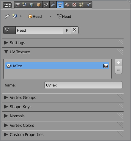
Before you can create an actual UV texture mapping, you need to add a slot for it on your mesh. You do this in the UV Texture panel in the Mesh Properties window. Note that you can add more than one UV texture. Unfortunately, multiple UV textures are beyond the scope of this book, but you should be aware that multiple UV textures are possible. You can also bake textures from one UV texture with one mapping to a different UV texture with a different mapping, which can be useful for removing visible seams. For now, simply click the + symbol once to create a single UV texture slot, as shown in .
Adding a new UV texture to the mesh
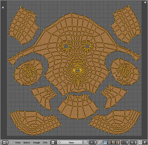
Next, still in Edit mode, select the entire head by pressing the A key. Move your mouse over the UV/Image Editor, and unwrap the mesh by pressing the E key. If your mesh structure and seam placement are exactly as described so far, then you should see mesh islands similar to the ones shown in . Their positions, sizes, and rotations may be different from those shown, but you can adjust this later.
From the Image menu in the UV/Image Editor, select New. In the dialog box that pops up, select the check box next to the UV Test Grid label. Leave the other values the same and create the image.
The unwrapped UV mapping
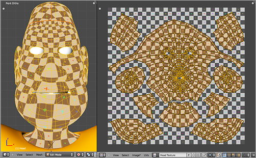
You should see a gray checkerboard pattern with small colored crosses appear behind your UV map. In the 3D viewport header, choose the Textured Viewport Shading option from the drop-down menu to the right of the Mode menu. You should see the test grid texture mapped to Captain Blender’s head, as shown in . At this point, you should save the image directly by choosing Save in the Image menu of the UV/Image header.
NOTE that changes to an image are not automatically saved when you save Blender. You must save edited or new images explicitly as images. As a hint to the user, an image that has not yet been saved will have an asterisk shown to the right of its name in the menu bar entry.
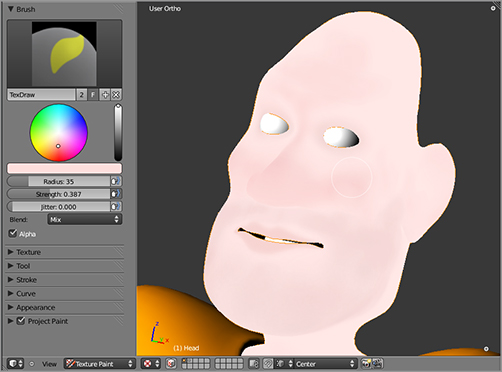
You can now begin to paint your texture using Blender’s Texture Paint functionality. To do this, simply enter Texture Paint mode with the drop-down menu in the 3D header. You can find the texture painting tools in the Tool Shelf of the 3D viewport by pressing T or by clicking the little plus sign widget in the upper-left corner of the 3D viewport. On the tool panel you can choose the type of brush by clicking directly on the brush-type icon at the top of the panel, you can choose the color of your texture paint with the color picker, and you can set the strength, size, and jitter level of the brush in the corresponding value fields. Brush strength and size can also be adjusted with the Shift+F and F hotkeys, respectively. shows texture painting in progress.
The mesh in with the default grid texture applied
Painting in Texture Paint mode
As powerful as texture paint is, sometimes you may want to do more advanced texture work, using photographs, alpha channels, more sophisticated brushes, or other effects. For these situations, you can edit your texture in the image-editing software of your choice.
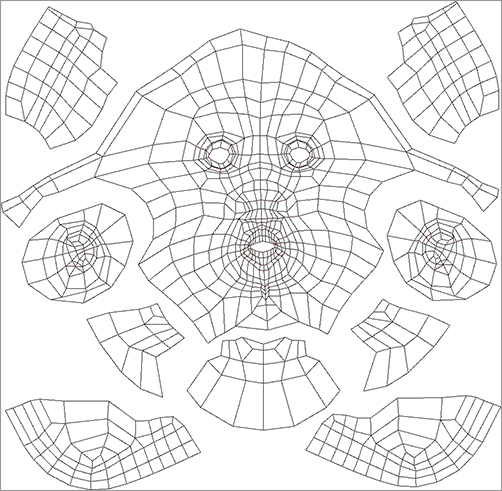
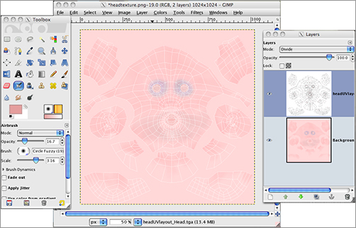
To refer to the UV map pattern while editing, you can export the UV map pattern using the Export script included in Blender. This is found under the UV menu in the UV/Image Editor header in Edit mode. The output of the exporter is an image file showing the UV mapping, as shown in . You can choose which kind of image file to export, but the default PNG format is a good choice. This can be imported into GIMP as a layer. Setting the layer to Divide mode will give you an overlay of white guidelines over the texture image, as shown in , so you can know exactly where the image corresponds to the mesh structure.
The exported UV map pattern
Getting back to Captain Blender, it’s now time to add another texture. The first texture you added was to control the mesh’s color, but color is only one of many surface characteristics that can be controlled with texture. You can control specularity, transparency, light emittance, and other characteristics with textures. One important use of textures is to control bump effects. This enables you to give the impression of bumpiness to a surface that is actually smooth.
In photorealistic skin texturing, bump mapping is used to create wrinkles, pores, bumps, and other skin irregularities that are far too small to model with actual vertices. With Captain Blender, you’re going for a much less realistic effect, so you’ll just use bump mapping for the eyebrows as an example of the process.
Editing the texture in GIMP
Begin by creating a new image in the UV/Image Editor. Do this in exactly the same way you created the color texture image, except rather than selecting the UV Test Grid option, leave the check box blank and create a plain black image, as shown in . Save the image with an indicative filename so that you know by sight that it is the bump map image.
Adding a new all-black image texture
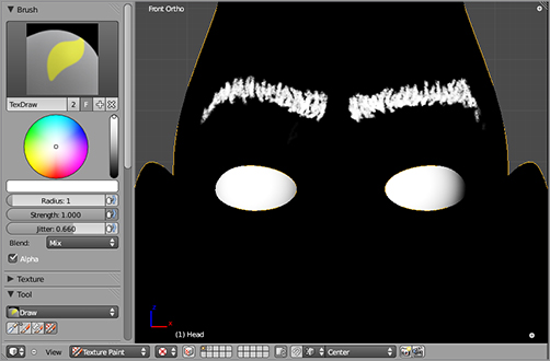
Once again, enter Texture Paint mode, and paint the texture. Use a fine brush size and white paint to paint eyebrows, as shown in . When you finish, save the texture.
Painting a bump map for the eyebrows
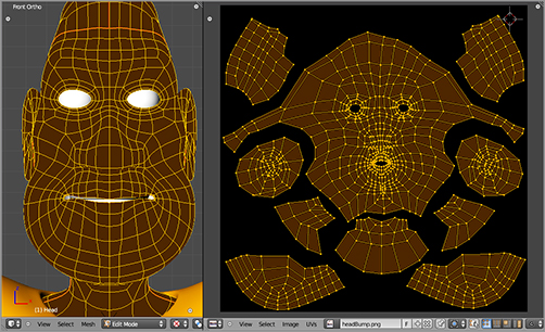
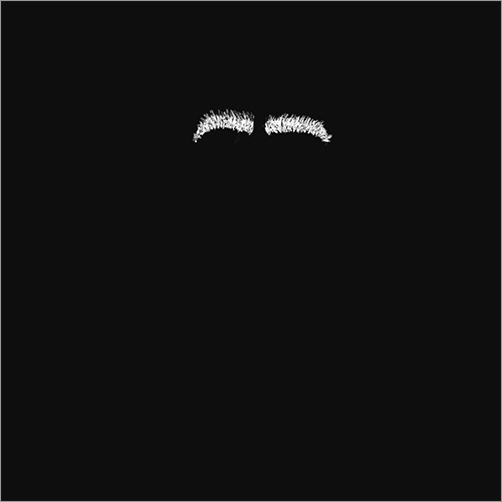
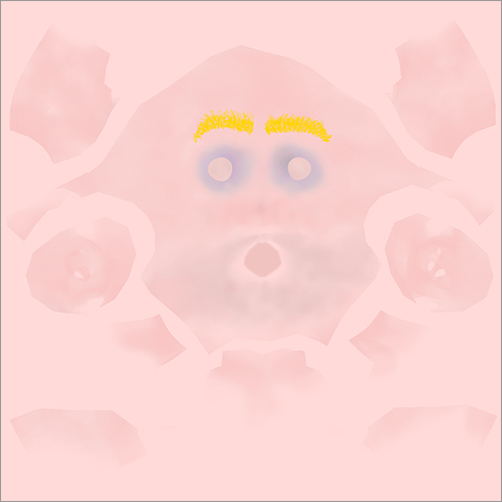
At this point, you should have two separate texture files saved on your hard drive: the bump map texture for the eyebrows and the color texture for the face, shown in and , respectively.
The finished bump map texture
The finished color texture
If you were to render an image now, you would find that Captain Blender’s head is the same dull gray that it was to begin with. You’ve created textures, but you have not applied them to a material, so the renderer cannot access them. To render these textures, first create a new material for the head just as you did for the body previously (if a material is already active on the mesh, you can just use that one).
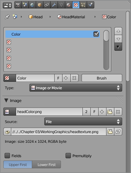
With the material slot selected, enter the Texture Properties window, and add a new texture slot (again, if there is already a texture slot there, use that one). Name the texture Color, and choose Image or Movie from the Type drop-down menu. In the Image panel, find the color texture that you saved on your hard drive. shows the Texture Properties window with all this done.
Scroll down the Texture Properties window to the Mapping panel, and choose UV from the drop-down menu.
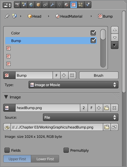
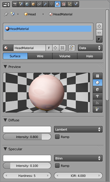
You’ll do the same with the bump map, placing it in the second texture slot and naming this slot Bump, as shown in . This texture’s Mapping value should also be set to UV. However, for the bump map, you must also adjust the Influence values. In the Influence panel, uncheck Color, and check Specular: Intensity and Geometry: Normal. Set those fields with values –0.8 and –0.6 respectively, as shown in . This will do two things: it will make the mesh shinier in the places where the texture is white (eyebrow hair is shinier than skin), and it will cause the white areas to appear to bump out from the surface of the mesh. shows the material values for the head material. Notice that the preview shows the texture applied.
Applying the color image texture to the material
Applying the bump image texture to the material
Influence settings for the bump texture
The material preview with the texture applied
Subsurface Scattering
No matter how realistic the color, bump, and specularity on a model is, there are certain characteristics of skin and tissue that cannot be represented with surface textures alone. In fact, skin and animal tissue (as well as many other substances such as wax, vegetable matter, milk, and certain kinds of synthetics) are slightly translucent and exhibit a property called subsurface scattering (SSS).
Subsurface scattering occurs when not all of the light that strikes a material’s surface gets reflected exactly at the surface. Some of the light penetrates the surface slightly and is reflected from a point within the surface. This creates a blurring (or scattering) effect. Real-life subsurface scattering is the main reason why a wax statue at Madame Tussauds is more lifelike than a plastic mannequin at Target.
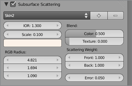
In Blender, you access subsurface scattering on the Material panel on the Subsurface Scattering panel. For the Captain Blender model, check the Subsurface Scattering check box, and choose the Skin2 preset, as shown in . I turned down the Color influence somewhat for this model. You should experiment with rendering with SSS activated to see the kind of results it produces. Getting a highly realistic SSS effect can be tricky, but it is an important effect if you’re looking for lifelike character models.
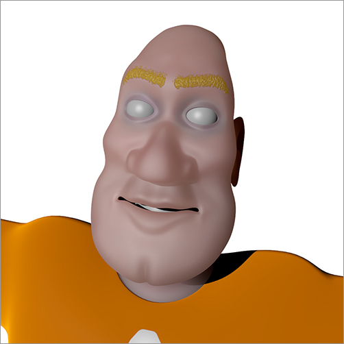
At this point, with the textures applied and SSS turned on, the rendered mesh should appear as shown in .
Adding subsurface scattering
The mesh so far
Eyelashes
So far, you have considered mesh modeling and texturing to be separate tasks. In some cases, however, the two tasks become especially interrelated. In the case of eyelashes, for example, you can use a texture itself to create the shape of the lashes. Using a 2D texture on planes is a common way of creating many hair effects. It doesn’t usually result in hair as realistic as the particle hair that you’ll see in the “Working with Particle Hair” section of this chapter, but it can be much easier to manage. Particularly in a simple case such as eyelashes, the benefits of working with simple textures often outweigh those of using particles.
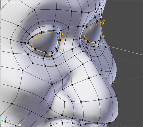
Because you must apply a texture to a mesh, you need to return briefly to mesh modeling to create a surface on which to apply the texture. You’ll start by selecting and duplicating the edge loops around the eyelids, which will be approximately where you want the lashes to be.
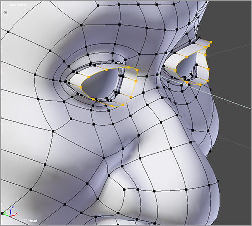
Select the loop by holding Alt while right-clicking an edge in the loop, and then copy the loop by pressing Shift+D. Move the duplicated edges out a bit along the y-axis to make them easier to work with, as shown in . Next, you’ll extrude the edge along the y-axis to give you the surface, as shown in .
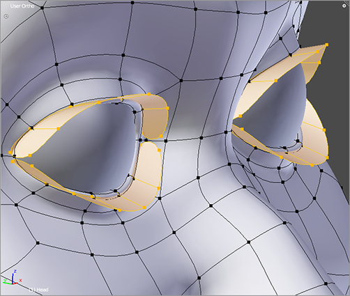
You’ll do a little tweaking now, separating the outer edges of the surface by selecting each edge and pressing the V key. Also, move the faces back toward the face and shape them in the way you want the eyelashes to be. Another important step here is to select all the faces and press Ctrl+N to recalculate the normals outside. Your results should look like .
Copying edge loop geometry to begin creating eyelashes
Extruding the eyelashes
Selecting the fully modeled eyelashes
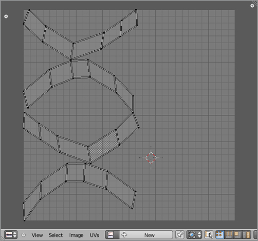
Select only the lashes by pressing the L key with your mouse over a vertex in each lash, top and bottom, right and left. The L key enables you to select connected pieces of mesh. Be sure not to select the entire head mesh; you’ve already unwrapped that part, and you don’t want to remap it. With only the lashes selected, press the E key in the UV/Image Editor to unwrap the lashes, as shown in .
HOTKEY: L key selects a single connected section of mesh based on proximity with the mouse pointer in Edit mode.
UV unwrapping the eyelashes
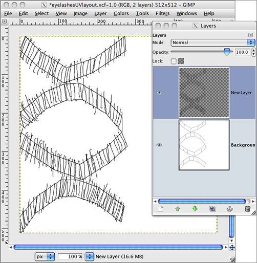
Export the UV map as described previously, and open the image in your 2D image-editing application. Add a new transparent layer and draw some simple eyelash lines on the new layer, as shown in . Save only the transparent layer with the lashes drawn on as your texture. Save the file as a PNG file.
Drawing the eyelash texture
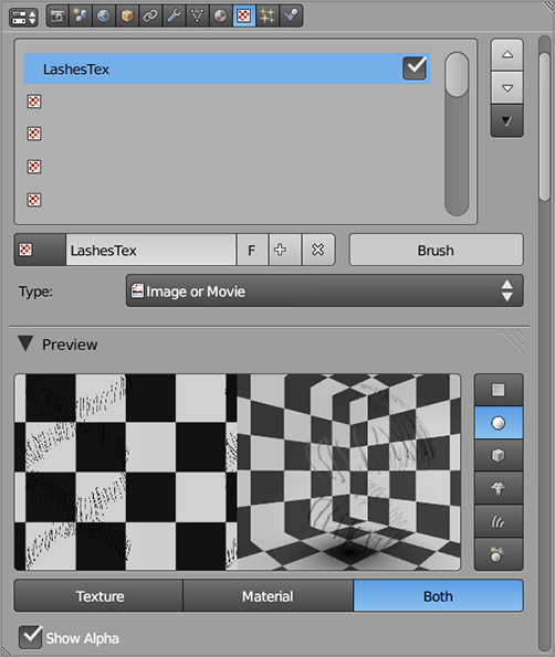
Create a new material and assign it to the mesh of the lashes, just as you have done several times so far in this chapter. Set the material color to Red: 0.615, Green: 0.289, Blue: 0.0. This will give us the reddish-brown color of the eyelashes. Set Specular Intensity to 0. Check the Transparency check box, and in the Transparency panel set the Alpha value to 0. Add an image texture to the material and load the PNG file you just created as the texture image. Choose UV for the Mapping type. If you check the Show Alpha check box on the texture preview, the resulting texture preview will appear as shown in . Set the Influence value of the texture to Alpha, with full (1.0) influence.
The eyelash texture
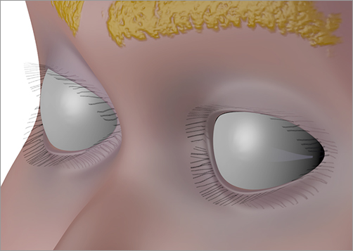
The lashes material is now finished, but you need to make a change to the head material to enable it to respond correctly to the shadows cast by a transparent or partially transparent material. Choose the head material slot, and in the Shadow panel for the head material select the Receive Transparent check box. The Receive Transparent option is necessary so that the mesh can take shadows from transparent objects correctly. By default, all shadows are treated as though they are cast by opaque objects, so in this case, the eyelash meshes would cast solid black shadows. Note that although transparency is a property of the eyelashes, the ability to receive transparent shadows from transparent meshes is a property of the object onto which the shadows are cast. When you’ve done this, the result should render out to look similar to .
The finished eyelashes
Controlling Materials with Nodes
When you briefly revisit the method described here to make the eyebrows, there’s something that doesn’t quite sit right. The bump-mapped eyebrows in themselves aren’t too bad, but the fact that the SSS effect on the head material is also being applied to the eyebrows is a little bit wrong. The result of this makes the eyebrows look more waxy and fake than they ought to look.
Unfortunately, you cannot control SSS with just a surface texture. However, using Blender’s powerful material node system, you can mix two completely separate materials on one mesh and use a texture to determine where each material is used.
To do this, first create a copy of the head material by selecting its slot and clicking the plus symbol to the right of the material slots field in the Material Properties window. Click the 2 next to the new material’s name to make it a single-user material. Rename it HeadMaterialNoSSS. Uncheck Subsurface Scattering, as shown in . Otherwise, leave the settings for the material the same.
Creating a copy of the head material without SSS

Add yet another material slot by clicking the plus symbol to the right of the slots. Once again, separate the material on this slot into its own single-user material by clicking the 2 next to it. This time, click the nodes button shown highlighted in to make the material a node material. A node material is a material whose characteristics are the final output of a node graph. The node graph can take multiple other materials or textures as inputs.
Adding a new node-based material
The hotkeys for adding and deleting nodes are analogous to adding and deleting elements in the 3D viewport. Shift+A brings up a menu of possible node types to add, and the X key deletes a node. When you create the node material, two nodes will automatically be created, a Material node and an Output node. The Material node is an input that can be an ordinary non-node-based material, and the Output node determines the characteristics of this node-based material.
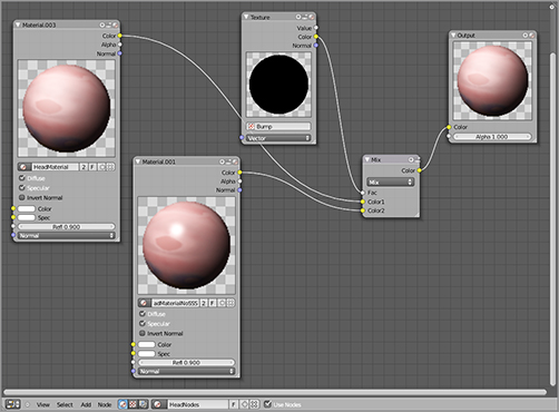
For this example, choose the original head material from the drop-down menu on the Material node. Add a second Material node by pressing Shift+A and selecting Input ⇒ Material. From the drop-down menu on this node, choose the HeadMaterialNoSSS material. Add a Texture node by pressing Shift+A and selecting Input ⇒ Texture. Select the Bump texture from the drop-down menu. Finally, press Shift+A and select Color ⇒ Mix to add a Mix node.
The idea is to mix the two materials together using the texture as a mix factor. Remember that the texture corresponds to the eyebrows, so it should describe exactly where the two materials should apply. The node network should be set up as shown in .
This is a very simple use of material nodes, but it should begin to give you an idea of how powerful they can be for creating complex materials and for mixing materials in a seamless and smooth way on a mesh. To delete a link between two nodes, hold Ctrl and the left mouse button, and drag your mouse across the link.
Mixing the two materials with nodes
Modeling Eyes
So far, our hero has been lacking one of the most important parts of a convincing human face: eyes. Now you’ll replace the blank gray orbs he currently has with some actual eyeballs. This process also involves a few additional steps of mesh modeling.
You’ll begin with those very orbs, because they are already the right size. To view the eyeballs on their own, select them in Object mode, and press the slash key on the numeric keypad to enter Local mode. You’ll now view only the eyeballs, and you can work with them without seeing anything else until the next time you press the slash key on the number pad.
Also, you’ll make only one eye and then copy it, so you can remove the Mirror modifier and recenter the object center on the single orb object. To remove the Mirror modifier, simply click the x in the upper-right corner of the modifier on the Modifiers tab. To position the object center, refer to “Object Origins” in Chapter 1.
So, now you’re working with a single UV sphere with 12 segments and 12 rings. Enter Edit mode to begin editing the mesh. Use the Loop Cut tool (Ctrl+R) to make a loop cut around where the iris will be.
The eyeball consists of two spheres, one inside the other. The outer sphere is transparent and models the clear lens in front of the iris and the specularity over the surface of the eyeball. The inner sphere will contain the colors and textures you want for the various parts of the eye. To make the two spheres, go back into Object mode, and duplicate the orb with Shift+D. Scale the new sphere down 1 percent by pressing S and immediately entering .99.
You’ll work with one sphere at a time, so let’s put them on separate layers for the time being. Enter Object mode, select the outer sphere, press M, and select any of the currently invisible layer buttons to put the sphere on that layer.
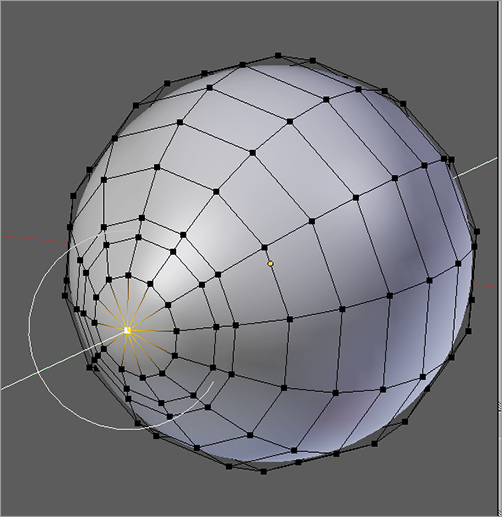
With the inner sphere selected, go into Edit mode, and create a concave indentation where the iris will be. Make sure you have proportional editing turned on with the drop-down menu in the 3D window header and set to Sphere Falloff. Then select the vertex at the pole of the sphere and use G, Y to move the point inward. Make sure to adjust the influence of the proportional editing tool with the mouse wheel so that only the nearest vertices are affected. You can see the influence of the proportional editing tool as a very light gray circle.
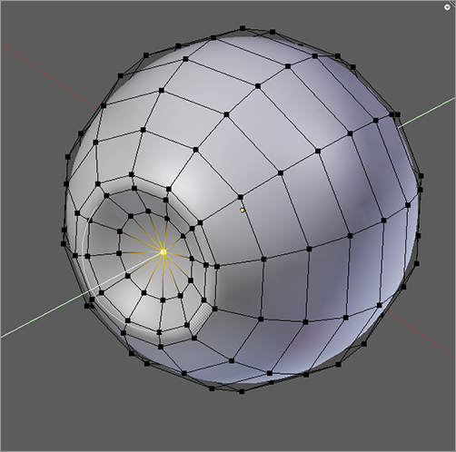
If you try to move the vertex and the whole eyeball moves, it is because the proportional editing tool’s field of influence is very wide. It might be too wide for you to see the circle in the 3D viewport. You might need to move the view out a bit to see the circle. Also, remember that you can adjust the proportional editing tool’s field of influence only while you are actually editing. You must press the G key first; then you can adjust the size of the circle. You should wind up with an indentation like the one shown in .
Modeling an indentation for the iris
That’s all the modeling you need to do on the inner eye. The real work here is done in the material, and specifically in textures. Create a new material slot, and name it EyeBall in the materials editing area. Turn the RGB values all up to 1, making the eyeball pure white. In the Specular panel, set Intensity to 0.
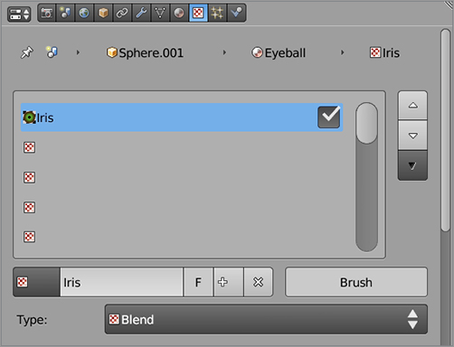
The iris and pupil will consist of three procedural textures layered on top of each other, which will together create the color, texture, and lightness and darkness of the eye. You’ll start with the basic color. Create a new texture in the top texture slot, and name it Iris. Set the texture type to Blend, as shown in .
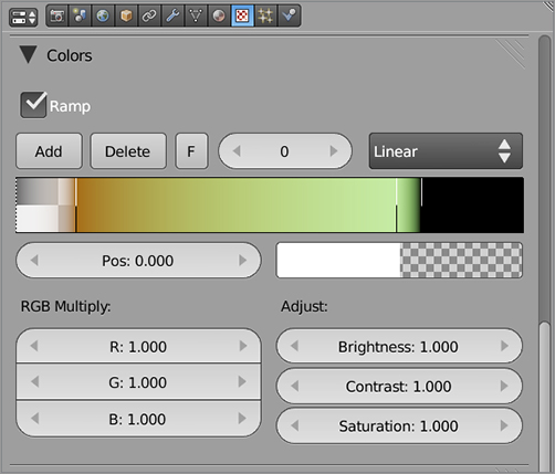
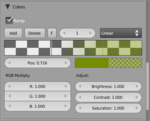
You’ll use the color ramp to control the color variation from the center of the pupil to the edge of the iris. Check the Ramp box in the Colors panel of the Texture Properties window and set your color ramp similarly to the one shown in .
You can add stops in the color ramp by clicking Add and adjust their color and alpha values with the color picker. The rightmost stop should be solid black, because it will be the iris. The leftmost stop should be white and should have an alpha value of zero. The colors in between are up to you, but I gave Captain Blender greenish eyes that blend into brown around the edges of the iris.
Adding the Iris texture
Adjusting the color ramp for the Iris texture
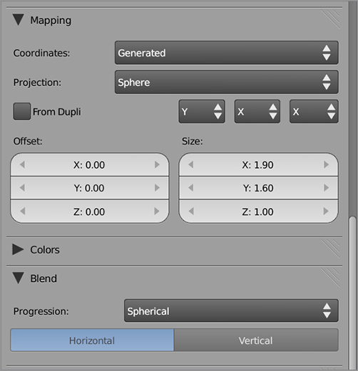
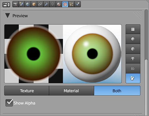
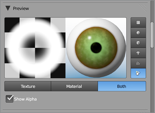
For the Mapping values, use Generated mapping and Sphere projection, as shown in . Also follow that figure in setting the projection coordinates to Y, X, and X. On the Blend panel, set the Progression value as Spherical. The resulting texture preview will look as shown in . Be sure to click the Both button under the preview window to see a preview of both the texture and the material it’s on side by side.
Mapping settings for the Iris texture
Preview of the Iris texture and material
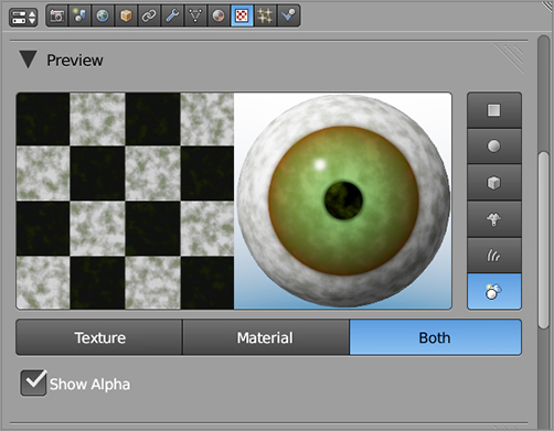
What you have so far is close but still lacks some character as an eyeball texture. Even from a distance, human irises do not look like smooth color gradations. You can fix this by adding an element of noise in the form of a cloud texture. Place this texture in the second texture slot. Adjust the Size value of the cloud texture to get an effect like the one shown in . Use the color ramp on this texture too to control the color and the steepness of the texture, as shown in .
The cloud texture
Color ramp for the cloud texture
Obviously, the problem here is that the cloud texture covers the whole eyeball, which is clearly not right. To fix this, copy the original Iris blend texture so that it is in the second texture slot, below the original blend texture and above the cloud texture. Adjust the ramp to be solid white, with the left and right sides both at Alpha 0. Check the Stencil box on the Influence tab. shows the stencil texture, alongside its effect. Notice that the cloud pattern on the eyeball is visible only in the area corresponding to the opaque portion of the stencil texture.
A stencil texture
You’ll now turn to the outer sphere of the eyeball. In Edit mode, with proportional editing turned on (the field of influence should be about the same as it was the last time you used it), select the pole vertex over the iris area, and pull it outward along the y-axis to create the slight bump of the eye’s lens, as shown in .
Shaping the outer sphere of the eyeball
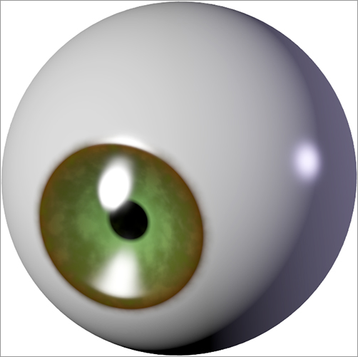
Create a new material for this object, and name the material OuterEye. Check Transparency, and set the Alpha value to 0. Use a Wardiso specularity shader with intensity at around 0.4 and a slope of about 0.12.
Your finished product should look something like when you render it. You can join the outer mesh and inner mesh by selecting both in Object mode and hitting Ctrl+J. Name the object Eyeball.L, and place it in the left eye socket. Then copy the object with Shift+D, and press the X key to move the new eyeball directly over to the right eye socket. Place it properly, and make sure it has the correct name.
The finished eyeball lit and rendered
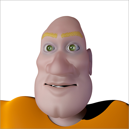
Congratulations. Your Captain Blender model now has clothing, skin, and eyes, as shown in . Something is still missing, though. In the “Working with Particle Hair” section of this chapter, you’ll see how to give your character convincing hair with Blender’s particle functionality.
Captain Blender with eyes
.
Selecting the scalp mesh
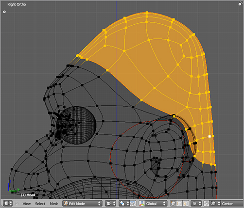
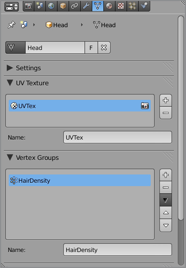
In the Mesh Properties window, scroll down to the Vertex Groups panel, and click the plus symbol to add a vertex group to the mesh. Name the group Hair Density, as shown in . Click the Assign button to assign the selected vertices to this vertex group. You will use this vertex group to control where the hair will “grow” from.
Adding a vertex group
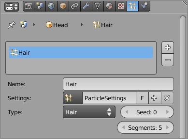
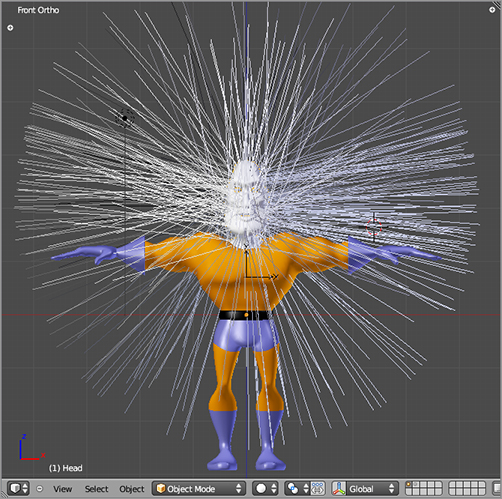
To set up the particle system, enter the Particle Properties window, as shown in , and add a new particle system by clicking the plus symbol, and then rename the particle system Hair as shown in that figure. Change the number of particles in the Emission panel from 1000 to 500. Your mesh should sprout hair, as shown in . Now it’s just a matter of bringing it under control!
Adding the hair particle system
The new hair
First, you need to constrain where on the mesh the hair emits from. For this, you’ll use the HairDensity vertex group you just created. Scroll down to the Vertexgroups panel, and enter Hair Density in the Density field, as shown in .
Controlling hair density with the Vertex group
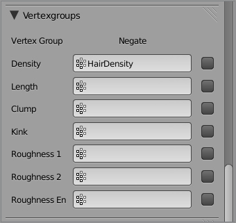
Notice that you can control any of seven different hair characteristics with vertex groups. Density refers to how many hair particles emit from faces based on their vertex group value. In this case, all the values for the HairDensity vertex group are 1 or 0, so either the faces will fully emit hair or they won’t emit any hair at all.
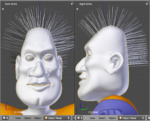
After you set the density vertex group, you should see the hair emit only from the scalp. Scroll back up to the Velocity panel, and change the Normal value from 1.0 to 0.2. This controls the length of the hair extending from the emitter face. After making these adjustments, Captain Blender’s hair should look more like . You’ll do further refining of the hair style directly in Particle mode.
Before you continue on to styling, activate child particles by scrolling down to the Children panel and clicking the Faces button. This will cause child particles to be emitted from the same faces that the actual particles are emitted from, increasing the apparent density of the particle system. Although 500 is really not enough particles to give the appearance of a full head of hair on their own, with child particles, it is more than enough. Set Display to 5 and Render to 80. This determines how many child particles per strand are shown in the 3D viewport in Object mode and how many are rendered.
A more reasonable starting point for hair styling
Styling Hair
You can style hair with a great deal of control in Blender’s Particle mode. However, once you begin styling the hair, many of the particle settings will be fixed, and you can change them only by discarding the edits you’ve made in Particle mode. You can adjust the number of child particles, for example, but you cannot change the number of actual particles without losing any hairstyling you’ve done.
Enter Particle mode using the mode drop-down menu in the 3D viewport header. Press the T key to open the Tool Shelf on the left side of the 3D viewport.
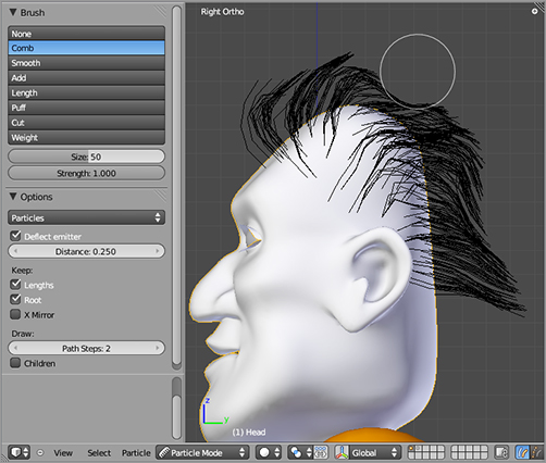
Hairstyling in Particle mode is simple, but it takes a little getting used to. You can select a “brush” type from the list in the Tool Shelf. A good one to start with is the Comb, as shown in . As you might imagine, this brush shapes the particle hair in a way analogous to the way a real comb shapes real hair. You must keep in mind that your edits are all happening in the plane orthogonal to the user’s perspective, so rotate your model frequently and style the hair from multiple different perspectives as you progress. If you spend all your time in orthogonal side view and get the hair looking just right, you may be surprised at how things look from the front.
Styling hair in Particle mode
The other brushes are Smooth, Add, Length, Puff, Cut, and Weight. All of these have to do with the shape or amount of hair except for Weight, which enables you to do weight painting directly on the hair. This is useful for softbody effects on hair. The Size and Strength fields affect the size and influence of the brush. The Deflect Emitter option keeps the hair from penetrating the mesh that emits it (some penetration can still happen, so be sure to make test renders and adjust the hairstyling where necessary). Keep Lengths and Keep Root will hold the lengths or root fixed when combing. If you uncheck Root, you will be able to comb the hair right off of the head.
In the 3D viewport header, you can select from three different selection modes. The default mode is Path Edit mode, which enables you to comb, grow, and edit the hair as a whole. The other two are Point Select mode and Tip Select mode.
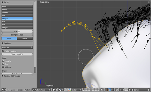
In Point Select mode, points along the length of the hair are visible as vertices, and you can select them in the same way that you select vertices in Edit mode. Furthermore, you can select individual hair particles using the L key. When particles are selected, only the selected particles are affected by the hairstyling tools. shows a few particles selected in this way, being styled to form a curlicue lock of hair over the forehead of the character. Without being able to select individual particles, it would be very tricky to achieve such an effect.
Selecting individual strand particles to edit
The third mode, Tip Select, is similar to Point Select except that you can select only the tips of the hair.
Hair Material and Texture
Hair particles will give you the shape and the density of the hair, but for really convincing hair, you need to be able to use materials and textures correctly.
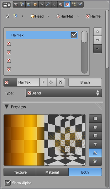
Create a new material slot, make the material single user, and rename the material just as you have several times before in this chapter. Name the newly created material HairMaterial. Add a blend type texture to this material called HairTex.
shows the HairTex texture preview. Select Show Alpha, and select the Strand material preview to see how the texture will show up on hair particles.
A blend texture for the hair material
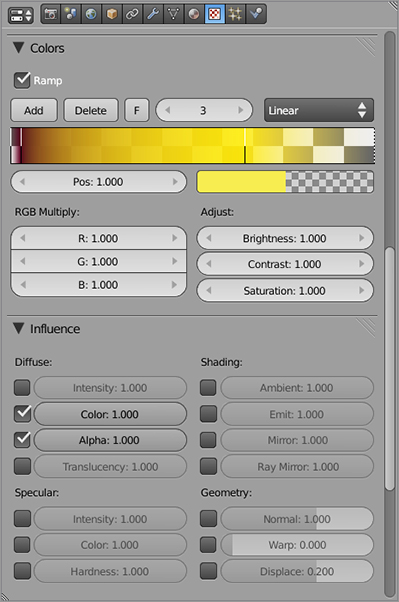
The blend gradation itself is defined in the Color panel, similarly to how you created the Iris texture for the eyes. Enable the color ramp by checking the Ramp check box.
The ramp stops vary in Color and Alpha values from left to right representing the alpha and color change from the root to tip of each strand of hair. For Color, I have the hair beginning with a darker brown root and lightening to an orangish blond color to the right.
The Alpha value is more important. The Alpha value must taper off gradually to the right to give a sense of wispiness to the tips of the hair. On the left, there should be a more sudden—but not too sharp—gradation from alpha 0 to 1. This has the effect of softening the appearance of the roots where the particles emerge from the scalp. If this didn’t have an alpha gradation, the roots would look very abrupt, giving the appearance of something more like bad hair plugs. The Influence settings of the texture should be full influence for Color and Alpha values. shows the Ramp and Influence panels.
The color Ramp and Influence panels for the blend texture
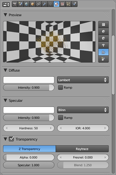
To receive the full alpha range from the texture, the material needs to have Transparency enabled and its own Alpha value set to 0, as shown in . Both Specular and Diffuse intensity values are turned up to 0.9, with Lambert set as the Diffuse shader and Blinn set as the Specular shader. You can experiment with these values until you find the effect you like best. Note again the Strand material preview.
The hair material
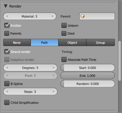
The material you just created is the third material on the head object. To set the hair particles to render with this material, you must select the corresponding material index in the Material field of the Render panel for the particles. This panel is part of the Particle Properties window and is shown in . Be sure that Emitter is selected (otherwise the Emitter object, Captain Blender’s head, will not be rendered) and choose Strand render, which will greatly speed up and improve the appearance of rendered hair.
Render settings for the hair
That’s all there is to it. When you render the head, you should see something similar to what’s shown in .
The mesh rendered with hair
You’ve now finished modeling and texturing your character. The next chapter will take you into the next phase of preparing your character for animation, as you are introduced to armatures and rigging.

