Chapter 2
Working with Meshes
In Blender as in many 3D animation programs, the basic object type in character modeling is the mesh. Two of Blender’s main tools of character animation, armatures and shape keys, are best suited for use with meshes. For this reason, although you can use other modeling techniques—such as NURBS, Bezier curves, and metaballs—animated characters that use these tools are typically created as polygon meshes in Blender. Perhaps because of this, Blender’s mesh modeling tools have attained a higher level of usability than its other modeling tools.
This chapter covers Blender’s main tools for organic mesh modeling. You’ll look at several different approaches, and by the end you will have built a fairly complex character mesh, which you will texture, rig, and animate in later chapters. If you prefer to skip these modeling tutorials and get straight to the next step, check the DVD for the appropriate .blend file to start with. The tutorials in this chapter should result in the same mesh that you will find in the CB-Model-base_mesh.blend file, so you can use that file to start on the next chapter’s tutorials. However, if you are interested in learning to model characters in Blender, follow the tutorials in this chapter before moving on, and use the .blend file as an additional reference.
- Polygons and Subsurfacing
- Poly-by-Poly Modeling and Box Modeling
- Common Problems and Solutions in Mesh Modeling
.
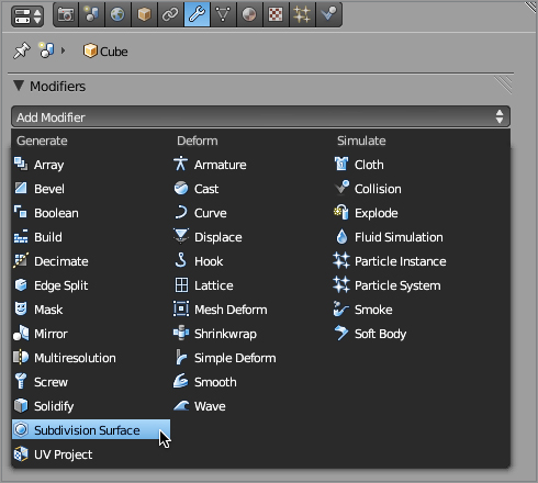
Adding a subsurf modifier
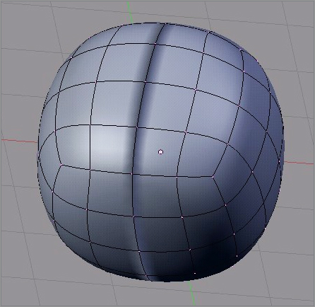
As you can see, with the subsurf modifier turned on with its view subdivisions value at 1, the cube’s surface takes on a different, smoother shape. In the View field under Subdivisions on the subsurf modifier panel, change the value to 2. Now you have something that begins to resemble a sphere. Optimal values for subsurfacing are 2 or 3 for the View field under Subdivisions and 3 or 4 for the Render field under Subdivisions, depending on the speed of your computer. Setting subsurfacing to be smoother when you actually render is a good idea. Higher values for these fields are unnecessary for the purposes of this book and can lead to serious slowdowns and even freeze your computer.
Although the cube now looks a lot smoother than it did before, it still looks like flat surfaces forming a sphere. To change this, you do not need to add more subsurface levels. Rather, you can simply change the way Blender calculates shading, giving the illusion of a smooth surface, by selecting Smooth rather than Flat under the Shading option on the Tool Shelf of the 3D viewport, as shown in . Do this on the Cube object, and you will see how much smoother it appears.
Shading options on the Tool Shelf
Let’s try the trick from Chapter 1 again, replacing the Cube mesh data with the Cone mesh data on the Cube object. A couple of things are worth noting. First, the Cone shape is now subsurfaced. The subsurf modifier acts on the Mesh object, and therefore swapping in new mesh data will not change the subsurfacing. You now have a subsurfaced Cone shape.
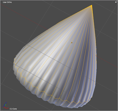
Second, you’ll notice that this subsurfaced Cone shape doesn’t look very good. At any rate, it’s not what you would call smooth, as you can see in . This is an illustration of a problem that one often hears about with regard to triangles and subsurfacing. Because of the nature of the subsurfacing calculation, triangles often do not subsurface smoothly, and the more elongated the triangles are, the more pronounced this problem is.
A subsurfaced cone made of triangles
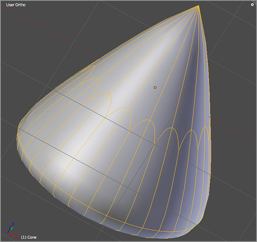
In general, conventional polygon modeling wisdom holds that triangles are to be avoided. As you can see in , the same cone subsurfaces much more smoothly when you make some cuts and change the geometry to quads. In fact, equilateral triangles subsurface reasonably well in many situations, but the reality of mesh deformations means that any triangle on your mesh in a place that is animated cannot stay equilateral all the time. For this reason, triangles should be avoided in visible places on your mesh that you intend to animate. At the time of this writing, polygons of more than four sides, known as n-gons, are not supported in Blender. A project is underway to extend Blender’s mesh modeling capabilities in this and other ways, but currently, quads and triangles are the only polygons that Blender supports. That means you’ll be using a lot of quads.
A cone modeled with quads
Blender Modifier System
As you just saw in the case of subsurfacing, you can impose certain qualities on a Mesh object by using modifiers. Modifiers let you alter an object in a nondestructive way. If you remove a modifier from a mesh, the mesh simply returns to its unmodified state. A wide variety of modifiers are available to create special effects, but in this book you will mainly be interested in the modifiers most pertinent to character modeling and animation. These modifiers include the following:
Subdivision Surfaces This modifier, often referred to as subsurf, adds virtual subdivisions to a mesh according to one of two algorithms. The default method of subsurfing uses an algorithm called Catmull-Clark to create rounded, smoothly curved surfaces from low polygon meshes. This method of subsurfacing is very important for organic mesh modeling.
Mirror This modifier displays a virtual mirror image of the mesh across a selected axis (the default is x). Mirrors are very useful for modeling symmetrical objects such as faces and bodies.
Lattice This modifier associates a mesh with a Lattice object, allowing for simple deformations of the mesh. A Lattice modifier is often used for distorting the shape of a mesh in unrealistic ways, and it is useful for cartoon effects such as stretching and squashing and bugging eyes.
Armature This modifier associates a Mesh object with an armature object for figure posing. Armatures enable more precise and constrained deformations than a Lattice modifier.
Mesh Deform Like Lattice and Armature modifiers, the Mesh Deform modifier is a tool for deforming a mesh. Mesh Deform modifiers let you deform one mesh by means of another Mesh object. The effect obtained with a Mesh Deform modifier is something between a Lattice and an Armature.
The concept of modifiers has expanded in recent Blender versions to include things that are usually dealt with elsewhere in the interface. For example, physics simulations and particles are all processed by Blender now as modifiers, but their settings are controlled in their own panels. They are modifiers insofar as their effect on the mesh is calculated according to the order they appear in the modifier stack, which you will learn more about in later chapters. Modifiers are also “nondestructive” in the sense that they can be deleted, leaving the mesh in its original, unmodified state.
The “traditional” modifiers you deal with directly as modifiers share certain options. You can toggle the display of the modified form of the mesh with these buttons, which are located to the immediate right of the modifier’s name.
The leftmost button toggles the display of the modified mesh in the rendered view, the next button to the right toggles the display in the 3D view window, the second button from the right specifically toggles the display of the modifier in the 3D view in Edit mode, and the rightmost button toggles whether the modifier is applied to the editing cage (the term for the visual representation of edges and vertices that you edit in Edit mode).
Most modifiers also have the options to copy and apply the modifier. The Copy function creates an identical modifier at the same place in the modifier stack as the original. The Apply function deletes the modifier and applies its effects to the mesh, creating a new, unmodified mesh, which is identical to the modified form of the original mesh. Be careful with this option. You usually do not need to apply a subsurface modifier, for example, and you should apply a Mirror modifier only when you have finished all edits that need mirroring.
As you create modifiers, they appear in order in a stack, which determines the order in which the modifiers’ effects are calculated. The up and down arrow buttons on the Modifier panel let you move the modifier up or down in the stack.
NURBS Modeling
Nonuniform rational B-splines (NURBS) are a way to define curved lines and surfaces that are more precise, more compact, and more restrictive in terms of modeling than subsurfaced meshes. NURBS is an older method for creating organic shapes using computer graphics, but since the rise of subsurface modeling, NURBS modeling has fallen from favor somewhat for character modeling purposes, depending upon the specific 3D application. Current uses of NURBS tend to focus on industrial design, where precision is more important than it is in character animation. (Precision measurement in general is not a strong suit of Blender, making it inadequate as a specialized CAD application.)
Blender has NURBS modeling capabilities, but it has much better support for mesh modeling. The only real reasons for a character modeler to use NURBS in Blender are to apply specific, personally preferred modeling methods and to follow habits acquired using more NURBS-oriented software. Another drawback of using NURBS for character modeling in Blender is the limitation on armature modification available for NURBS. Although NURBS surfaces can take armature modifiers, you cannot create vertex groups or do weight painting on NURBS surfaces, and armatures are limited to using envelopes to influence the surface. I’ll talk more about what this means and why it is so restrictive in Chapter 4. For now, it should suffice to say that meshes in Blender can be much more responsive to armatures than NURBS surfaces are.
There has been talk about improving Blender’s NURBS editing functionality for years, but I wouldn’t advise anybody to hold their breath for it. Even if such improvements are made, it is unlikely that this would significantly affect how character modeling is best done in Blender.
You can create NURBS primitives by pressing Shift+A to add an object and selecting Surface or Curve. The tools available for modeling with NURBS are broadly analogous to those available for mesh modeling (although there are far fewer).
Modifier Effects
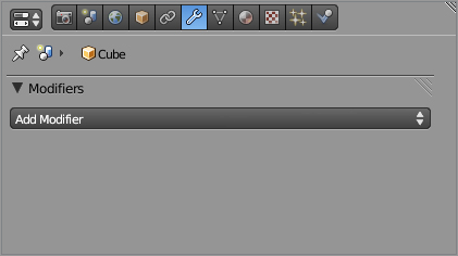
To see an example of how the resulting mesh can differ according to the order in which the modifiers are applied, create a new file in Blender, and select the default cube. On the Modifiers tab, choose Add Modifier ⇒ Mirror.
On the Modifier panel, select the Clipping option. Now enter Edit mode. By default, all vertices should be selected. Move the entire cube one Blender unit (BU) to the right along the x-axis. To do this, press G and X in succession, and hold down Ctrl while you move the object with the mouse to turn on incremental snapping.
As you move the cube to the right, you will see the cube’s mirror image moving to the left. When you have moved the cube half its own width, the cube and its mirror image will be flush with each other, as in (a).
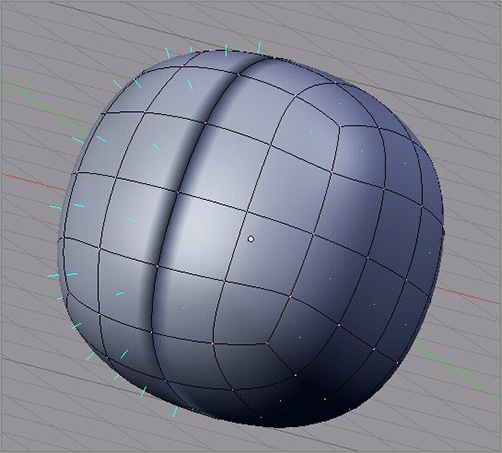
Now, add a subsurface modifier in the same way you added the Mirror modifier. Set the View subdivision level to 2. You should end up with the peanut-like shape you see in (b). This is because the mesh being subsurfaced is not the original cube but the mirror-modified cube.
If you want to subsurface the original cube and mirror-modify the resulting mesh, you need to bump the subsurface modifier up so it is calculated before the Mirror modifier. Do this by clicking the up arrow on the subsurface modifier (or the down arrow on the Mirror modifier). The resulting modified mesh, as you can see in (c), is two separate sphere shapes.
You can now try applying the modifiers. You must be in Object mode to apply modifiers, so tab into Object mode first. Also, be sure to apply the top modifier first, or your results may be unexpected. If you apply both of these modifiers, you wind up with a single Mesh object, whose mesh consists of two sphere shapes, as in (c). If you edit this object, you will see that each vertex is an independent, fully editable, real vertex.
The effect of modifiers on meshes: (a) a mirrored cube; (b) the cube mirrored and then subsurfaced; (c) the cube subsurfaced and then mirrored; (d) the mesh with the modifiers applied
You will look more closely at the various modifiers and their uses later in the book.
Vertex Size
You might notice that the vertices shown in the illustrations here are larger than the ones on your computer. This is done for legibility in print, but if you want to change the vertex size on your own computer, you can do this on the Themes tab of the User Preferences window. Scroll down to the bottom of the Themes settings to find the Vertex Size field.
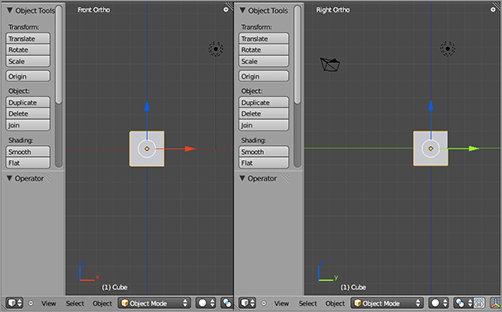
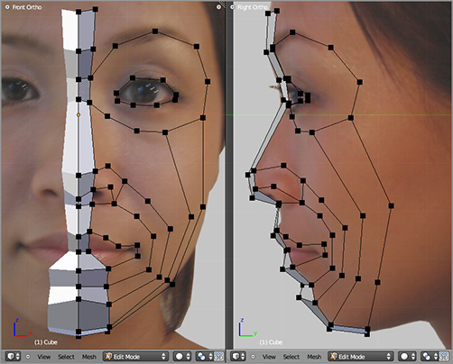
. The label in the upper-left corner of the right window reads “Right Ortho.” It’s a little confusing, because this is in fact a view of the cube’s left side, but the labeling is based on the viewer’s perspective. You can enter the reverse view of each of the number pad views by holding Ctrl while you press the number pad key.
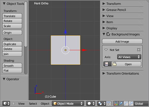
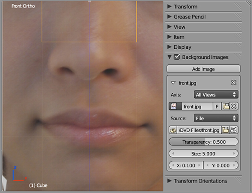
To add a background image to a 3D viewport, you need to access the Properties Shelf for the viewport, which you can do either by clicking the small round button in the upper-right corner of the viewport or by toggling the shelf with the N key. In the Properties Shelf, you’ll find a Background Images check box. Drill down into the panels here with the triangular icons until you’ve found the Open button, as shown in .
Two viewports in front and side orthogonal views
Accessing the Background Image panel in the viewport Properties shelf
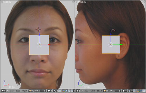
Click Open, and you will see a file browser. Navigate to the image you want on your hard drive, and click Open. For the left viewport, use the image front.jpg from the book’s companion DVD. Make adjustments to the X offset value on the Background Images tab so that the centerline of the 3D viewport is as close as possible to the middle of the face, as shown in , where the X offset value has been adjusted to 0.1. For the right viewport, follow the same steps but use side.jpg. The resulting viewports should look like . Note that in the figure I have hidden both the Properties Shelf and the Tool Shelf for both viewports. You can toggle these shelves’ visibility with the N key and the T key, respectively, or just drag them out of view with the mouse.
Adjusting the X offset value of the background image to center the face
3D viewports with background images
Because you will begin modeling with a Mirror modifier, the model will be perfectly symmetrical. Real faces are not perfectly symmetrical, so over the course of the modeling, it might be necessary to adjust this X offset to account for the difference and to keep the model as close to the overall face as possible. Nonsymmetrical modeling has to be done later.
If you plan to create your own background images, keep in mind that Blender calculates the default size based upon the width of the photograph. For this reason, it is simplest to work with photographs with the same height and width. The best thing is to crop your background image in an image manipulation program such as Gimp or Photoshop in such a way that the eye line, nose, and lips line up as closely as possible. There will almost always be inconsistencies in the view caused by perspective and slight shifts in the position of the subject. Another alternative is to put both front and side views on the same image, as you’ll see done in the Captain Blender tutorial later in this chapter.
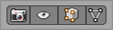
Now that you have the background image in place and the views organized, you can get started modeling. You won’t be using the manipulator while modeling, so you can toggle it off in the 3D viewport header to get it out of the way. Pressing Ctrl+spacebar will also toggle the manipulator visibility.
To edit the mesh, first select the Mesh object by right-clicking it, and then tab into Edit mode. The cube’s vertices are now selectable and editable.
You’ll begin by deleting the back face of the cube, leaving you with just the front face pane. This is best done in the side view viewport, in transparent, or in wireframe view mode. To toggle wireframe view mode, press the Z key, which toggles between wireframe and solid display mode.
HOTKEY: Z key toggles between wireframe and solid display mode.
When you are in wireframe mode, vertices that would not be visible in solid mode are visible and selectable. The A key toggles selection between all vertices and no vertices. To select the back face of the cube, first ensure that no vertices are selected by toggling with the A key, and then press the B key to initialize box selection and drag your mouse so as to surround the vertices with the selection box. The resulting selection will look like .
HOTKEY: B key initializes box selection.
Select all vertices with the A key. Still in the side view viewport, scale the selected portion of the mesh down by pressing the S key and moving the mouse.
HOTKEY: A key toggles all items in the view selected and unselected.
HOTKEY: S key scales the selection.
Selecting the rear face of the cube
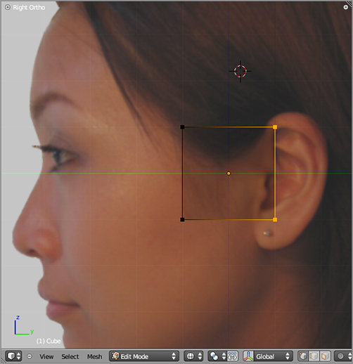
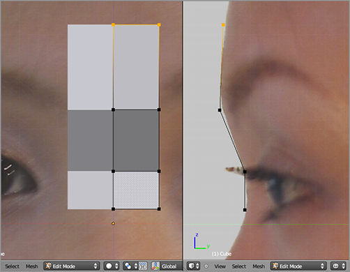
When you have scaled to the size you want, click to confirm the transformation. Then move the selection to the bridge of the nose, as shown in , by pressing the G key and moving it with the mouse. Click to confirm the transformation.
The selection scaled and moved
The process of rotating, scaling, and grabbing (moving/translating) vertices, edges, or faces is analogous to performing those transformations on objects. The hotkeys are R, S, and G, respectively, and you can constrain the transformations to the x-, y-, or z-axis by pressing the corresponding hotkeys. As in the case of objects, the left mouse button confirms the transformation, and the right mouse button cancels it.
When modeling things such as faces or human bodies that are largely symmetrical, it helps to be able to model only one half and to let Blender mirror the model automatically. You do this by using the Mirror modifier mentioned previously.
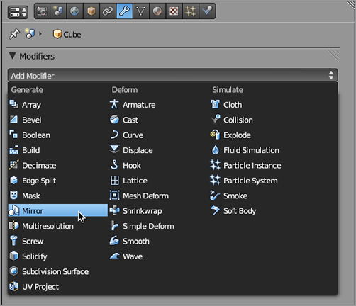
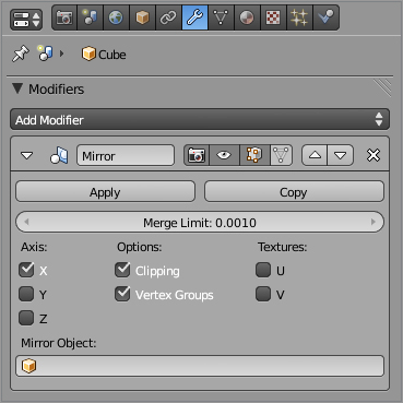
You can activate the Mirror modifier now by clicking Add Modifier in the Modifier properties panel, as shown in . When the drop-down menu appears, select Mirror, as shown in . Leave most of the Mirror modifier settings at their default values, but select Clipping, as shown in . This option clips the seam between the two mirrored halves of the model together, preventing the model from splitting or overlapping along the center line. As you will see later in the modeling process, there are times when you want this and times when you don’t.
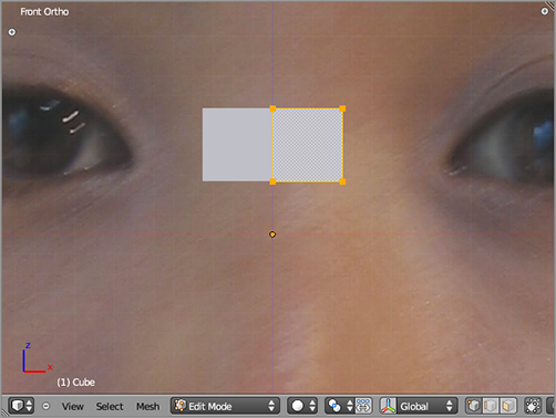
In the 3D viewport, looking at the scene from the front view, select the vertices of the plane with the A key if they aren’t already selected, and move the plane to your right, away from the center by pressing the G key and dragging them with the mouse, as shown in . You will see the mirrored mesh move the opposite direction. Note that no matter how far you pull the vertices from the center, the centermost vertical edge between the mirrored half remains clipped to the center. This happens because Clipping is active on the Mirror modifier.
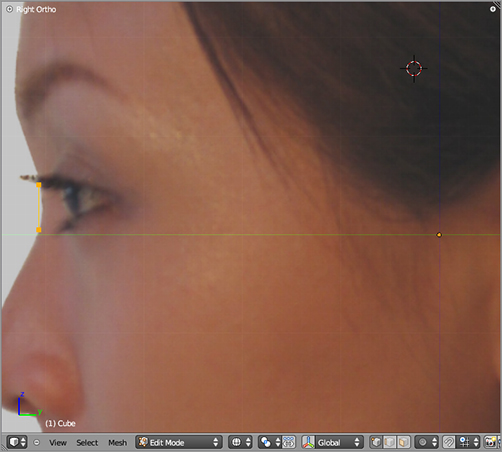
Now you’ll begin modeling with extrusion. This is the heart of poly-by-poly modeling. Make sure all vertices are deselected with the A key, and then select the top edge of the plane by holding the Shift key and right-clicking the two top vertices. In the side view window, extrude this top edge by pressing the E key. Extrude again to follow the contour of the forehead, as shown in .
The Modifier properties panel
Adding the Mirror modifier
Mirror modifier settings
Moving the mirrored plane away from the center
HOTKEY: E key extrudes new geometry from selected geometry.
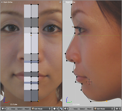
Next, do the same thing with the bottom edge of the plane, extruding downward 10 times to follow the contours of the face down past the chin, as shown in . Do these steps in the side view, but keep an eye on the front view to make sure everything is where it should be from all angles.
Extruding the top edge over the forehead
Extruding the bottom edge over the lower part of the face
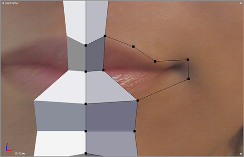
In the front view, adjust the position of the vertices around the mouth. Select the single vertex at the top edge of the lip, and extrude (E key or Ctrl+click) four new vertices around the edge of the mouth from the top of the lip. You can add an edge between any two vertices by selecting both vertices and pressing the F key. Do this to connect the last of the four extruded vertices to the bottom edge of the mouth. shows the result.
HOTKEY: F key in Edit mode creates an edge between two selected vertices and creates a face when three or four vertices are selected.
Modeling the shape of the mout
When you are extruding the lip outline, you might not see your changes mirrored on the left side of the model. If this is the case, you are probably viewing in Solid mode, which displays only mirrored faces. Pressing the Z key shows the wireframe model properly mirrored. If the modifier is set to apply to the editing cage during Edit mode, then the wireframe model will always be visible.
With the drop-down in the header of the 3D viewport, activate Proportional Editing with a Sharp falloff so that the selected icons appear as shown here.

Proportional editing causes unselected vertices within an area of influence to respond to edits on selected vertices. The influence diminishes according to the curve of the falloff type you select for the Proportional editing tool. The area of influence is represented by a circle and can be adjusted with your mouse wheel. You can turn proportional editing on and off with the O key and iterate through falloff types by pressing Shift+O.
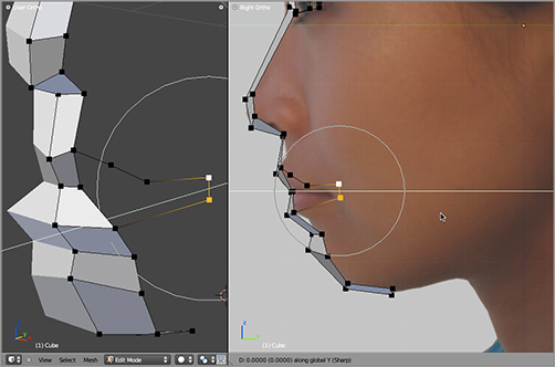
With proportional editing active, select the vertices at the corner of the mouth and pull them back along the y-axis by pressing the G key to grab them and then the Y key to constrain the translation to the y-axis. As you can see in , the vertices of the entire mouth should move in conformance with the proportional editing curve. If too many or too few other vertices move, adjust the circle of influence of the proportional editing tool with your mouse wheel.
Translating the edge of the mouth along the y-axis with proportional editing
Now that you know how to extrude vertices with the E key or Ctrl+click and how to create an edge between two vertices with the F key, you should have no trouble adding some more geometry to the mesh.
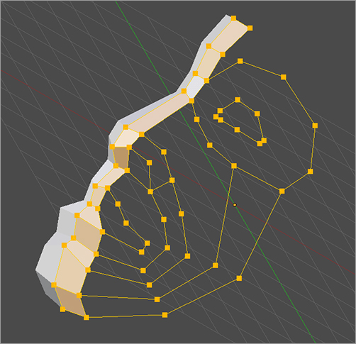
Disable proportional editing, and add the vertices and edges shown in . Be sure to keep an eye on both the front and side views so that the shape stays accurate from all angles. From time to time it’s a good idea to check your work from other angles, as shown in .
Hold the middle mouse button to rotate your view, and then press 1 or 3 on the number pad to get back to the front or side view, respectively. When you leave the orthogonal views, your background image will disappear, but don’t worry, it will appear again when you get back into the front and side view modes.
Take note of the geometry you’ve begun to construct at this point. You have already established several important features, which are important regardless of what modeling technique you use. Both the eyes and the mouth are already being constructed of loops. As you continue to model, you will keep the eyes and mouth in this form. When you model a different character later using box modeling, you will still make sure that the mouth and eyes are loops and that the loops extend and overlap in a way that includes the nose and cheeks within an unbroken pattern of loops. This is important from an animation perspective. You might be able to get away with different underlying geometry for a still model, but if you intend to animate facial expressions, you’ll find that the human face is unforgiving in terms of the necessary geometry.
Adding vertices and edges
Checking the work from various angles
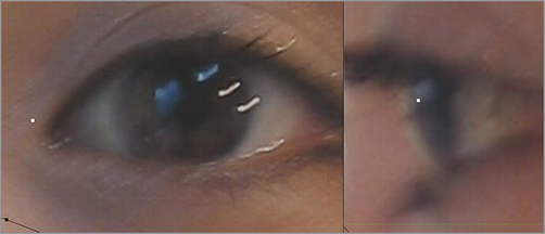
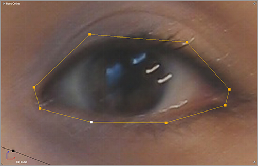
You need to make the eye outline now. To do this, create a vert in front view by Ctrl+clicking with no verts selected, as shown in . You can extrude from this vert to create the outline of the eye, as in . Complete the last edge by selecting the first and last vertices and pressing the F key. Once again, the number of verts shown is important because you will later need to connect the eye to rest of the face, so be sure to follow the example exactly.
Adding a single vertex at the inner corner of the eye
Outlining the eye with vertices
Geometry, Topology, and Loops
The term geometry refers to the vertices that make up a mesh and specifically their placement in the 3D space. The term topology refers to the structure created by the edges and faces that connect the vertices. Identical-looking meshes can have different underlying topological structures, and for beginning modelers it is easy to get caught up in making the shape look right, at the expense of paying attention to the actual structure. When making models for animation, however, it is very important to consider the topology of the mesh because it will determine how the mesh deforms when you begin to add shapes or poses.
Topology is important because of the way the edges and vertices provide “tension” by holding the surface in place. Think of an umbrella: an open umbrella is shaped something like a hemisphere, made of cloth and held in its shape by a topology of edges extending from the tip. You can construct a similar hemisphere of cloth by using concentric rings, for example, but such a structure clearly does not fold like an ordinary umbrella. This is somewhat analogous to how edges influence the deformation of a mesh. To get the correct topology, you must consider what deformations you want from the mesh.
Loops are continuous sequences of edges (edge loops) or faces (face loops) that define the surface of a subdivided form. Loops might completely encircle some section of the mesh, but this is not necessarily the case. Not all edges or faces are part of a loop. You can select edge loops in their entirety by using Alt+RMB; you should try selecting a few edges in your model in this way to get a sense for what Blender recognizes as edge loops. Loops are very important in facial modeling; without correct loop structure in the face, it is very difficult to get good facial deformations. Good loop structure is especially critical in the mouth and nose area.
For the best deformations, the flow of the loops should approximately follow the shape of the muscles of the face because they determine how the shape of the face will change and the directions along which the skin will stretch. As you progress through this tutorial, you should pay close attention to the way edges and faces create loops. Further study of facial anatomy and musculature can also be very helpful.
Fix the shape of the eye outline to follow the eye in the background image by translating the appropriate verts along the y-axis, as with the rest of the face.
Next, begin to fill in the faces. To fill in a face, you select its four vertices and press the F key, as shown in .
Adding a face between four vertices
The faces you fill in will also appear in the mirrored portion of the model. Fill in the faces, four verts at a time. Fill in the faces as shown in .
More faces filled in
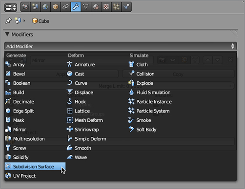
At any point in the process, you can add a Subdivision Surface (subsurf) modifier to generate a smoother, more rounded mesh. In most cases, you can model equally easily with or without subsurfing, so it is a matter of personal preference at what point you add the modifier. Try adding it now.
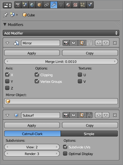
To add the subsurf modifier, go to the same Modifier Properties area in which you added the Mirror modifier, and select Subdivision Surface from the Add Modifier drop-down menu, as shown in . The modifier will appear in the modifier stack below the Mirror modifier, as shown in . In the fields below the Subdivisions label, change the View value to 2 and the Render value to 3. These values determine how smoothly the model will be displayed in the 3D viewport and during rendering. The values 2 and 3, respectively, are usually ideal.
Adding a subsurf modifier
Settings on the subsurf modifier
When you add a subsurf modifier after editing a mesh’s geometry, you may find that ugly black artifacts appear, such as those shown in . The location of these artifacts depends on factors such as the order in which the faces were created, so it’s likely that artifacts on your model will be different. These artifacts are caused by inconsistent normals; adjoining faces are facing opposite directions. To fix this, enter Edit mode, select all the vertices with the A key, and press Ctrl+N to make the normals consistent.
Artifacts caused by inconsistent normals
Continue with the model by extruding the edges of the forehead, as shown in , and the side of the face, as shown in . Connect the geometry with a face, as shown in .
Extruding the forehead geometry
Extruding geometry for the side of the face
Adding a face at the temple area
Now turn to modeling the nose. Begin by selecting the faces shown in and extruding them with the E key, as shown in .
To form the nostrils, you need to adjust your Mirror modifier settings. Currently, you have Clipping selected. With Clipping selected, mirrored faces extrude together, as they did when you extruded the tip of the nose a moment ago.
Selecting the faces that make up the tip of the nose
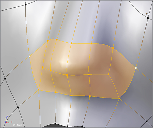
Extruding the tip of the nose
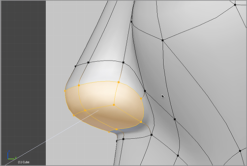
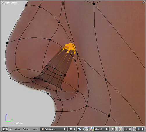
For the nostrils, however, you want to extrude mirrored faces as individual faces. So, uncheck Clipping in the Mirror modifier properties panel, and then extrude the faces as shown in to begin forming the nostrils. Scale them down slightly. Extrude again, viewing from the side as shown in , and pull the inner faces up and inward. Scale them down slightly to complete the basic modeling of the nostrils. Once you’ve done this, go back to the Mirror modifier properties and turn Clipping back on.
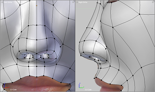
When you have the basic topology done, you can push the vertices around until you’re satisfied with the shape of the nose, which should look something like .
Extruding and scaling the nostrils
Extruding the nostrils inward
The finished nose
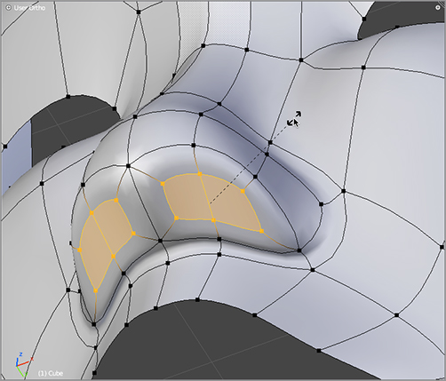
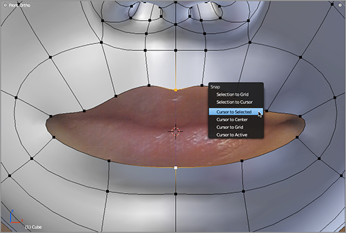
Next you’ll turn to the lips. To model the lips, you’ll use the 3D cursor as a pivot for scaling. To place the 3D cursor where you want it, select the middle vertices at the top and bottom edge of the lips, and then press Shift+S to display the snap menu and choose Cursor To Selection, as shown in . Be careful not to inadvertently place your 3D cursor somewhere else by clicking. If you do this, you’ll need to select these vertices again and snap the 3D cursor back where you want it.
HOTKEY: Shift+S key brings up the Snap menu.
Snapping the 3D cursor to the point between two vertices
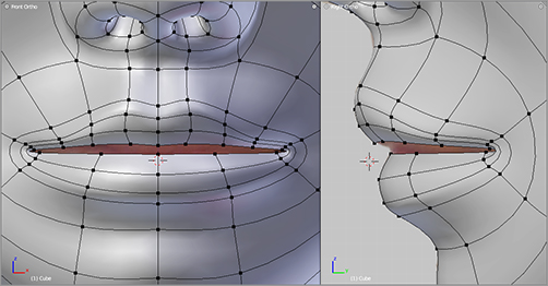
Select the edge loop around the lips by holding the Alt key and right-clicking any edge in the edge loop, and then extrude a total of three times to create the lip geometry shown in . Each time you extrude, you will need to scale down slightly by pressing the S key and then scale down slightly more along the z-axis (vertical) by pressing the S key followed by the Z key. Move the vertices as necessary to create a pleasing shape for the lips.
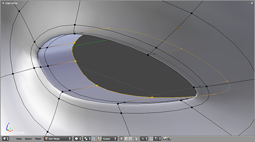
To model the eyes, begin by cutting a loop around the eye using Ctrl+R, as shown in . Then extrude the edge of the eye three times, as shown in . The sharp edge of the eyelid is formed by extruding, scaling down slightly, and then extruding again and translating along the y-axis slightly. The last extrusion brings the edge farther into the head where it will be hidden by the eyeball.
HOTKEY: Ctrl+R initializes the Loop Cut tool in Edit mode.
Extruding, scaling, and translating edge loops to form the lips
Cutting a new loop around the eye
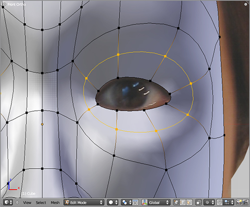
Extruding the loop of the eyelids
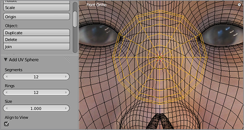
You can’t do much more modeling around the eye area without knowing exactly where they eyeball will be positioned, so now is a good time to add the eyeballs. Do this in Object mode so the eyeballs will be a separate object from the head mesh. In the front-view 3D viewport, add a sphere by pressing Shift+A and selecting UV Sphere. Set the values for Segments and Rings at 12 in the fields on the Tool Shelf to the left of the 3D viewport, and select Align To View, as shown in . If the object is not already centered, then center it by pressing Alt+G. Alt+G places the object so that its center point is in the origin of the 3D space.
HOTKEY: Alt+G clears the transformation for the selection.
Adding a sphere for the eyeballs
Add a Mirror modifier to the sphere, leaving Clipping off. Add a subsurf modifier to the eyeballs also, with the same settings as the one on the head mesh. In Edit mode, scale the mesh down and move it into place, as shown in . The eyeballs will probably not fit perfectly in the face, but place them where you think they belong. You will need to enter Object mode, select the head mesh, and enter Edit mode to edit the mesh around the eyes in order to make the face fit the eyeballs properly, as shown in .
Mirroring and positioning the eyeballs
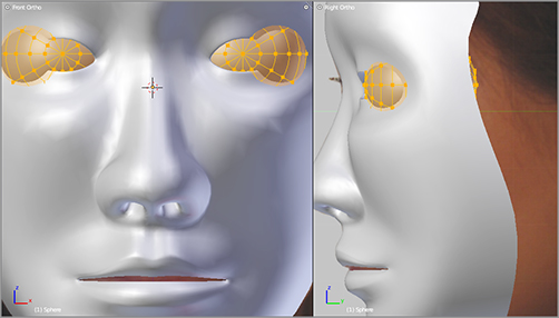
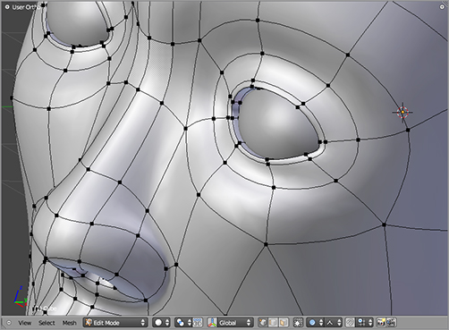
Adjusting the face mesh to accommodate the eyeballs
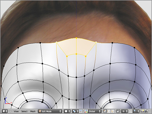
Extrude some geometry for the neck down from the chin as shown in , and then add a face to the forehead as shown in . With the geometry as it is so far, it is straightforward to extrude and model the remainder of the head, as shown in and . When you’ve finished with all these steps, your model should look like .
Extruding the front of the neck
Adding a face to the forehead
Extruding the forehead to create the shape of the head
Filling in remaining geometry
The finished model
There’s not enough room in this book to go into detail about modeling ears for this character, so I’ll leave that as an exercise for you to experiment on your own. Look at photographs and your own ears in the mirror, and try to create mesh ears with topology that follows the shape you want to model. There’s no right way to do it; if it looks good, it is good. Also, remember that ears are not usually animated, and there are lots of hidden nooks and crannies where you can hide the odd triangle, so it’s OK to take some liberties.
The Mirror modifier works by making a mirrored duplicate of the mesh you’re working on. After you apply it, these vertices become real. Adding another Mirror modifier creates a new set of mirrored verts. If this is edited, the original unmirrored mesh remains unchanged, resulting in a variety of mesh problems. For this reason, it is not advisable to add a new Mirror modifier after you have already applied one. One way around this limitation is to delete half the mesh before applying the second Mirror modifier. However, it’s a good idea to try to get all your symmetrical editing done before applying the Mirror modifier. If you’re not sure you’ve done this, it might be best to save a backup file before applying the modifier.
Introducing Captain Blender: From Mild-Mannered Cube to Superhero
In the next section, you will create a whole comic book–style character using box modeling; you will then have the basis for the character model that you will work with and build on throughout the book.
Although you can use some variation of poly-by-poly modeling, because you want to focus on the overall shape of the body early on, box modeling is a good option. In contrast with the previous tutorial’s example of starting with the details of the face and working outward to the shape of the head, box modeling lets you quickly work out the proportions and then focus on smaller and smaller areas of detail.
Note again that these methods are not exclusive to each other. You can model the head using poly-by-poly modeling, model a body using box modeling, and then attach the head to the body. After you become accustomed to mesh modeling in Blender, you will find your own favorite approaches to modeling various kinds of objects and characters.
Getting Started: Legs and Feet
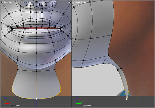
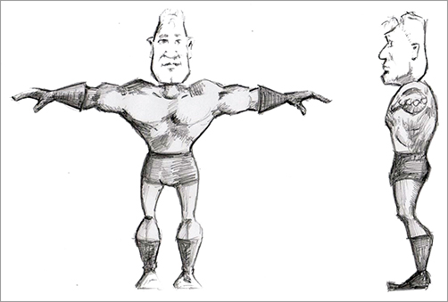
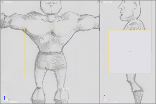
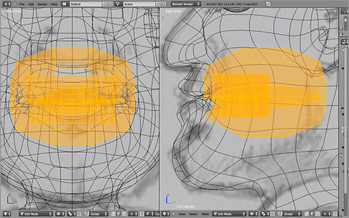
To create Captain Blender, you’ll begin in the same way you did when you modeled the face, with two 3D viewports—one in orthogonal front view and one in orthogonal side view. A small difference is that in this case, there is only one image file for the background, which includes both front and side views of Captain Blender, as shown in . You’ll load the same file as the background image in your front and side views, but in the side view you will need to adjust the x-axis offset for the background image so that the profile image is properly lined up with the cube when shown from the side, as shown in .
Front and side view character sketches
Front and right ortho views with background images
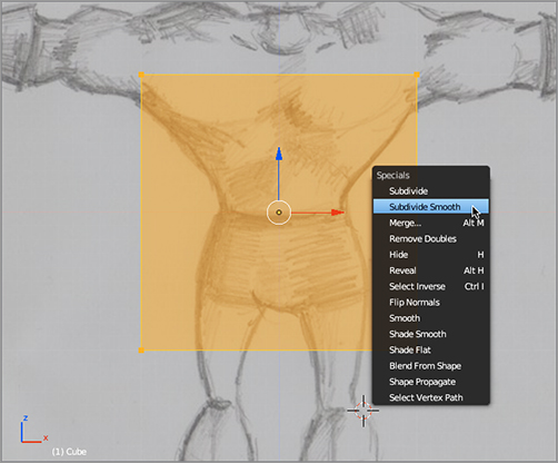
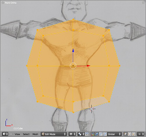
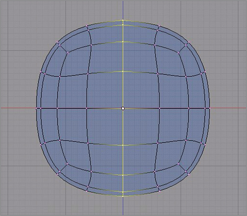
When box modeling, I find that a smooth, subdivided cube is a great way to start. Tab into Edit mode, select all the vertices of the default cube by pressing the A key, and then press the W key to bring up the mesh Specials menu. Select Subdivide Smooth, as shown in . The result will be a slightly rounded subdivided cube, as shown in . This shape will form the basis of the torso, so scale and translate it to fit approximately to the torso of the character. You scale with the S key and translate with the G key. Remember that you can scale along a specific axis by pressing the S key followed by the key of the axis you want to scale along. So to elongate the shape vertically, press the S key, and then press the Z key. Scale and translate the mesh as shown in .
HOTKEY: W key brings up the Specials menu specific to the mode you’re in.
The Subdivide Smooth operator in the mesh Specials menu
The subdivided cube
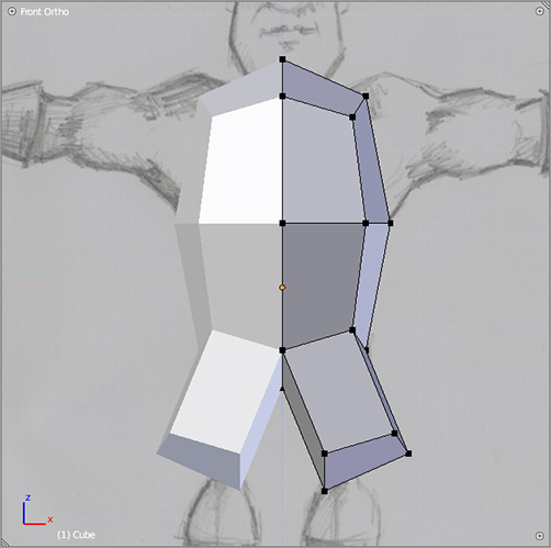
Next, you’ll begin modeling a leg. To do this, you’ll extrude the two faces on your right on the bottom of the subdivided cube. To select both the front-facing and back-facing faces, be sure that the mesh view is wireframe (transparent) in your front-view 3D viewport, and select the vertices using the Box Select tool. You access the Box Select tool by pressing the B key and dragging the mouse so that the dotted box surrounds the vertices you want to select. If you do this in solid (opaque) view mode, only the front-facing, visible vertices will be selected. In this case, you want the vertices on the back to be selected too. When you’ve selected the two faces in this way, press the E key to extrude the base of the leg, as shown in .
Adjusting the location and scale of the mesh
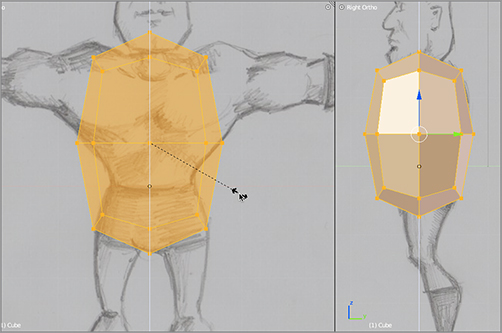
Extruding a leg
Now that you’ve extruded the base of one leg, it’s almost time to add the Mirror modifier. Before doing this, however, you need to delete half the mesh so that the mirrored portion will not overlap. Do this by selecting the vertices on the left side using the Box Select tool and pressing the X key (select Vertices from the Delete menu), as shown in . Be sure to select the vertices in wireframe view so that you delete all vertices in the front and back. Add the Mirror modifier in the same way you did for the head model in the previous section, and select the Clipping option. shows the resulting mirrored mesh.
HOTKEY: X key deletes the selection.
Deleting half the mesh
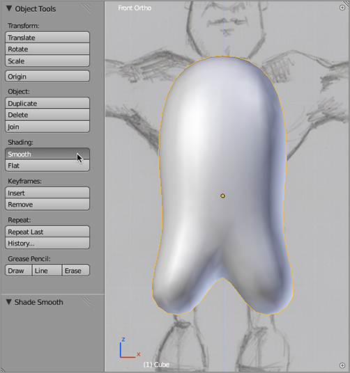
This is a good time to add the subsurf modifier also. Add the modifier in the same way you did in the previous section with the head model. In Object mode, select the Smooth shading option in the Tool Shelf, as shown in . Tab back into Edit mode to continue editing the mesh.
Cut a vertical loop in the mesh using the Loop Cut tool. You access Loop Cut with Ctrl+R, and you set the location of the loop by moving your mouse over an edge perpendicular to where you want the loop cut. When you do this, a purple loop cut indicator will appear, as shown in . You can adjust the number of cuts made by this tool using the mouse wheel, but just one cut is fine here. Confirming the cut with the left mouse button will cut the mesh and add the new vertices, as shown in .
The mirrored mesh
The subdivided mesh with smooth shading
Making a loop cut
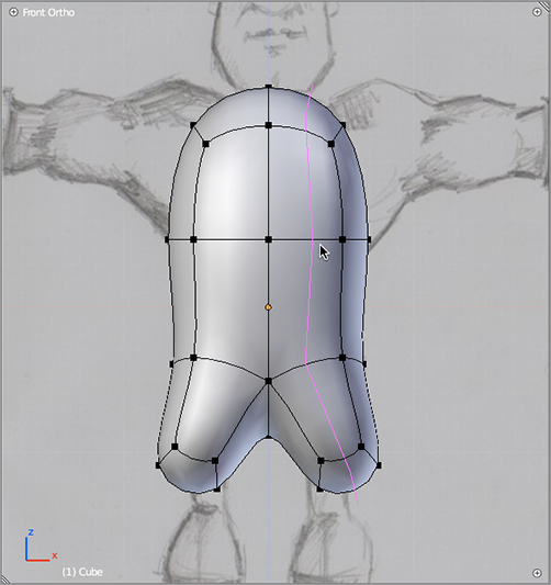
The resulting mirrored loop cut
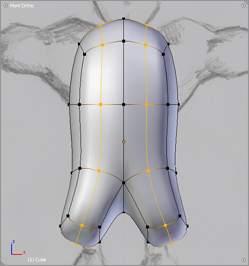
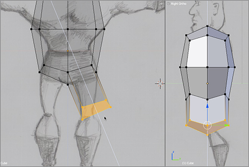
Select the faces at the end of the extruded leg, as shown in , and extrude them twice to the ankles, scaling as you go, to get them shaped, as shown in . Adjust the location of the vertices of the leg to round off the shape, as shown in .
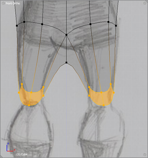
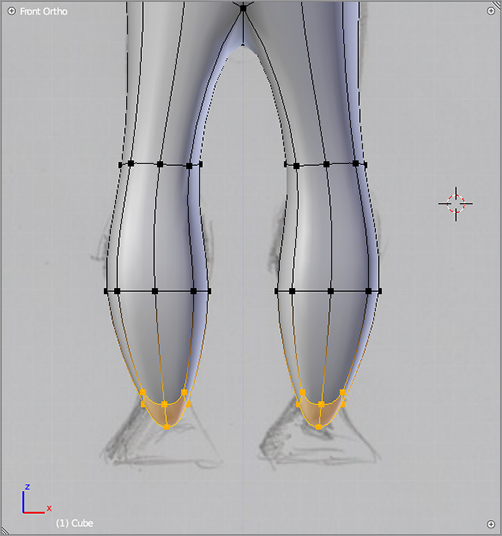
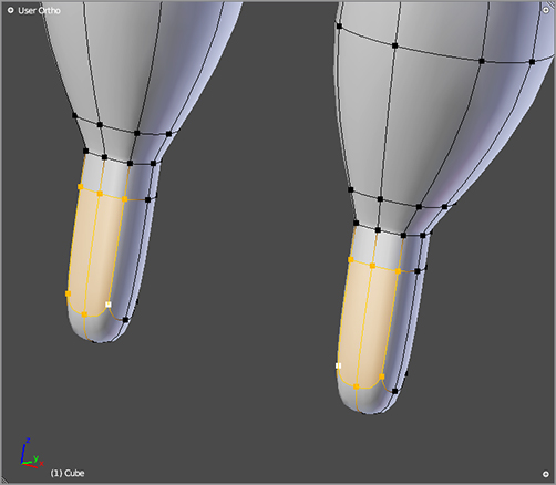
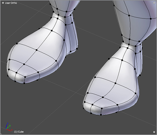
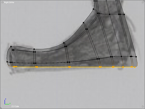
Extrude three more times downward to create a base from which to extrude the foot. Select the front faces of this shape, as shown in , and extrude four times forward along the y-axis. Shape the mesh as shown in to create the feet. To flatten the soles of the feet, select the bottom faces of the feet and extrude with the E key, as shown in . Scale the extruded vertices to 0 along the vertical axis by pressing the S key followed by the Z key followed by 0. This has the effect of flattening the geometry vertically.
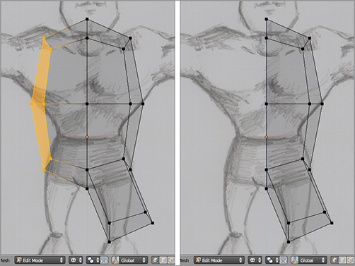
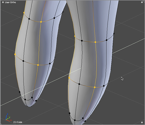
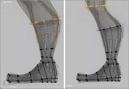
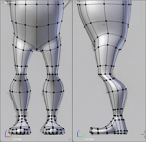
Adjust the vertices of the legs, as shown in , to form the knees and calves. Remember that you can select complete edge loops by holding the Alt key while right-clicking an edge in the loop. Being able to scale, rotate, and move a whole edge loop at once is very useful in making these kinds of adjustments. In the same way, shape the rest of the legs so that you end up with something similar to what’s shown in .
Moving the leg vertices downward
Extruding the lower legs
Shaping the legs
Preparing to extrude the feet
The extruded and shaped feet
Extruding the soles of the feet
Tweaking the leg shape
The legs so far
Torso and Arms
This section will focus on Captain Blender’s upper body. As before, you will make a lot of use of loop cuts and extrusions. Keep in mind what kinds of deformations you will want from the character when you come to animating him. This decision will influence how you model the arms.
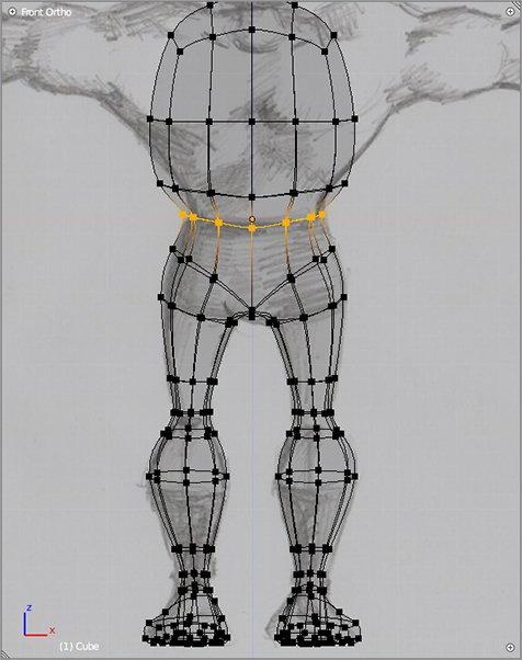
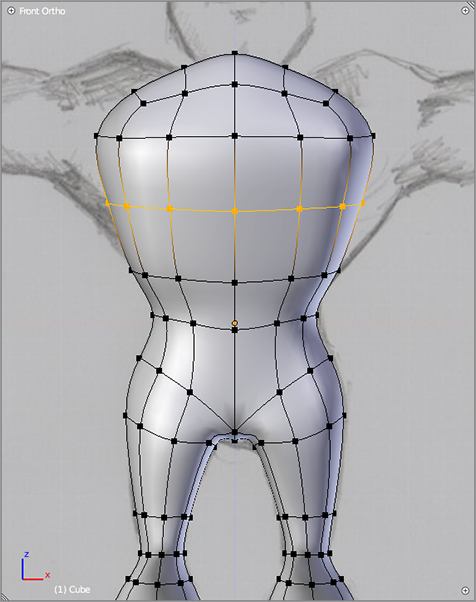
To begin with, you’ll need to add some new geometry to the torso to give you something to work with. Do this by cutting a loop around the belly, as shown in , and another loop around the chest, as shown in . Remember that the Loop Cut tool is accessed by pressing Ctrl+R and then putting your mouse over an edge perpendicular to the loop you want to cut.
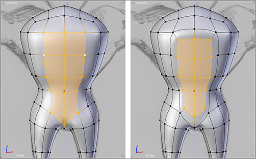
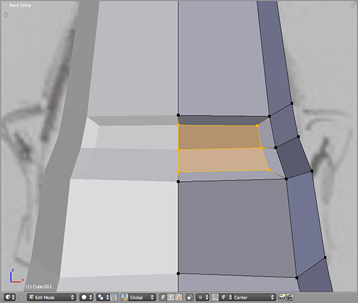
Select the eight faces that make up the front of the abdomen, extrude with the E key, and then scale with the S key, as shown in . This is another way to add vertices to work with.
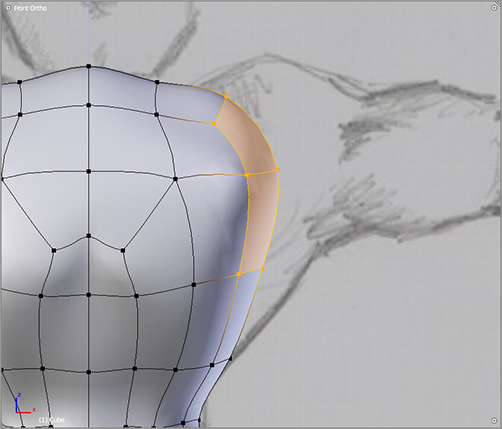
Select the shoulder faces (both front and back), as shown in . Extrude six times, bringing the extruded vertices down the length of the arm and scaling the circumference of the mesh arm appropriately, and then activate proportional editing and twist the tip of the arm around the x-axis using rotation (R key), as shown in .
A loop cut at the belly
A loop cut at the chest
Selecting and extruding faces on the abdomen
Preparing to extrude the arms
Extruding the arms and twisting with the proportional editing tool
Hands and Gloves
This section looks at the details of creating the hands and the flared gloves. Once again, you will use all the techniques of the previous sections, while adding a few new ones, such as separating polys using the Rip tool and stitching mesh segments again by creating faces.
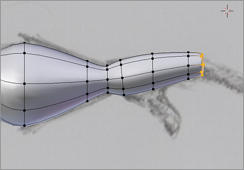
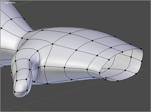
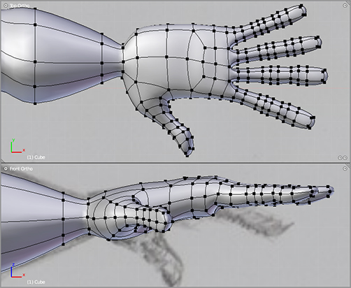
Continue where you left off at the tip of the arm, and extrude the base shape of the hand. This consists of five extrude operations from wrist to where the base of the fingers will be, as shown in .
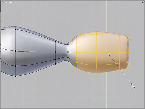
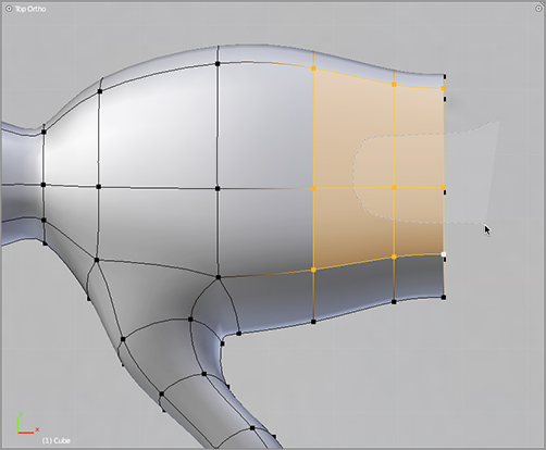
Scale the width of the hand along the y-axis by pressing the S key followed by the Y key. shows this operation viewed from above (notice the Top Ortho label in the upper-left corner of the figure). You can enter the top ortho view by pressing 7 on the number pad. Extrude and scale the base of the thumb as shown in . Extrude three more times to the full length of the thumb, and move the vertices around to adjust the shape of the thumb. Then delete the vertex at the very tip of the appendage so that the mesh at the base of the fingers is open, as shown in .
Extruding the basis of the hand
Scaling the shape of the hand along the y-axis
Extruding the thumb
Deleting the endmost vertex
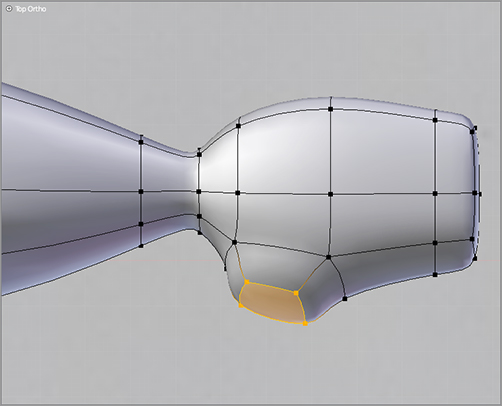
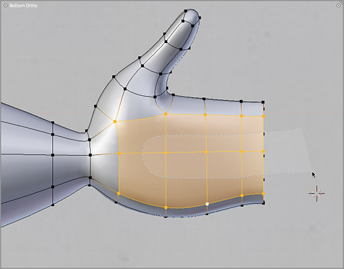
Again in top view, select the four topmost faces on the back of the hand, and cut them in a U-shape, as shown in with the knife tool. Access the knife tool by pressing and holding the K key while click-dragging the mouse over the edges in the mesh you want to cut. When you’ve made the cut on the back of the hand, view the mesh from below by holding Ctrl and pressing 7 on the number pad (all number pad views can be reversed by holding Ctrl when you choose them). Select the eight faces that make up the palm of the hand, and cut them in a U-shape, as shown in .
Cutting vertices into the back of the hand with the knife tool
Cutting the palm of the hand with the knife tool
Close the open end of the hand with faces, as shown in . As you should recall from the poly-by-poly modeling example previously, you create faces by selecting four vertices at a time (Shift+right-click) and pressing the F key. You will select these eight new faces two by two to form the basis of the four fingers.
Select each pair of faces, and extrude nine times along the length of the fingers. Scale the circumference of each finger appropriately. You can adjust the rotation of each finger by selecting all of its vertices and rotating the whole finger with the R key. Likewise, the G key will let you grab and move the geometry to get the placement just right. The resulting fingers should look something like the ones shown in .
HOTKEY: R key rotates the selection.
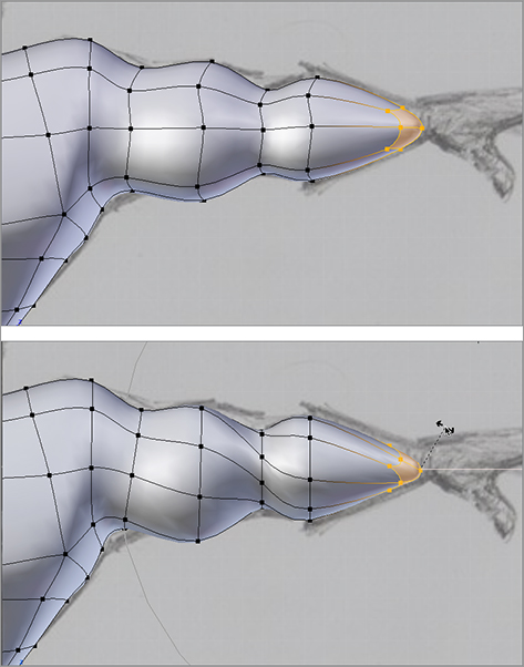
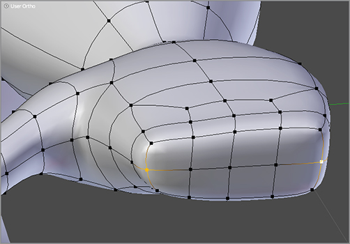
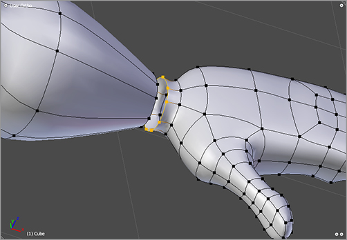
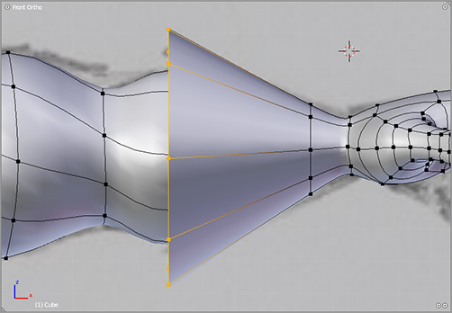
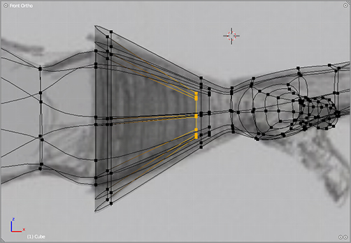
To create the flared glove, you’ll need to rip the mesh. Select the edge loop just up from the wrist by holding Alt and right-clicking an edge in the loop. Rip the mesh by pressing the V key. This will separate the edge loop into two, as shown in . Extrude from there to create the glove flare, as shown in . Extrude again and scale down slightly to give the glove some thickness, and then extrude once more and pull the new loop in to double back inside the glove, where it will be hidden by the arm mesh, as shown in .
Filling in the end of the hand with faces
Extruded fingers
Ripping edges at the wrist to create the glove
Extruding the glove
Extruding the glove inward
Collar and Belt
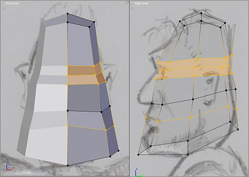
In this section, you’ll model the collar and the belt. The collar will give you the chance to see how you can use extrusion to create tightly creased forms, such as the place where Captain Blender’s neck meets his suit. The belt will be a separate Mesh object.
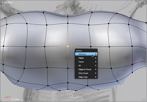
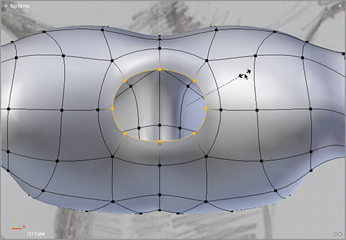
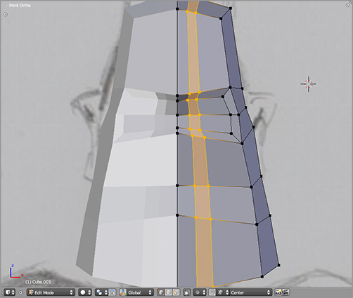
To create the collar area, delete the vertex at the top of the mesh, where the neck of the character should be, as shown in . Select the edge loop around the hole where the vertex has been removed, extrude, and then scale downward, as shown in . Extrude three more times: on the first extrusion scale down slightly, on the second extrusion drag the edge loop downward slightly along the z-axis, and on the third extrusion drag the extruded loop down farther, where it will eventually be hidden by the neck of the character.
Deleting the vertex at the neck
Extruding and scaling vertices around the neck
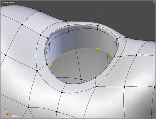
Extruding and translating vertices to complete the neck of the costume
At this point, you’re finished with the main body Mesh object for Captain Blender. Other parts of the character will use separate objects. It is no problem to use multiple objects for a single character; in fact, it is often much easier to treat separate items of clothing or body parts as separate objects.
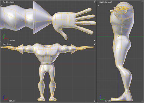
Before you go on to modeling other objects, take a look at the model you have, and compare it with the model in . Make sure that the shapes look right and the geometry is all there. Add edge loops if necessary.
Views of the body
Captain Blender’s trusty utility belt is made of an extruded circle. Scale the belt to fit as shown in . In the same way that you can constrain transformations to particular axes by pressing X, Y, or Z, you can constrain the transformations to particular planes by pressing Shift+X, Shift+Y, or Shift+Z to constrain to the plane perpendicular to the specified axis.
Modeling the belt from a circle
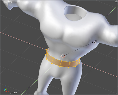
So, in order to constrain your scaling to the xy plane, as illustrated in , use Shift+Z. When you have the belt the right side, extrude the whole thing to give some thickness and scale down again on the xy plane. Delete the inside faces of the belt.
When you’ve finished modeling the belt, enter Object mode, select the body mesh, and apply the Mirror modifier. This makes the virtual, mirrored vertices real, and they are now independently editable. After you have applied the Mirror modifier, select the belt object, and then hold Shift while selecting the body object. The order of selection is important here because the last object selected will be the object that everything else is joined to. Press Ctrl+J to join the two meshes.
That takes care of the body. You’ll model the head as a separate object in the next section.
Modeling the Head
Now let’s turn to the head. As mentioned previously, the head will be a separate object. To concentrate on modeling this object without getting distracted by the modeling you’ve already done, you can do this work on a separate layer.
Blender’s layer functionality lets you create visibility groups that you can toggle on and off as you like. The default scene is all located in the first layer, and only the first layer is set to be visible by default. Switch to the second layer by clicking the second button in the layers button bank on the header of the 3D viewport, as shown in .
Switching to layer 2
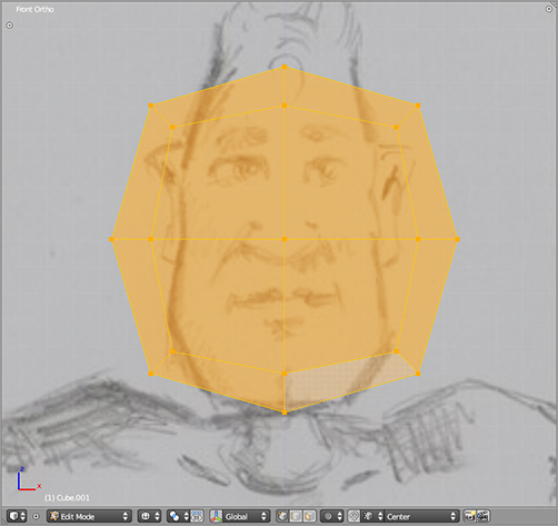
Add a new cube by pressing Shift+A and choosing Mesh ⇒ Cube from the Add menu. Press Alt+G and Alt+R if necessary to clear any translation or rotation from the new object. Tab into Edit mode, and subdivide-smooth the mesh in the same way that you did previously to begin modeling the body (the W key will open the mesh Special tools menu when you have a mesh-type object selected and are in Edit mode). Grab and scale the subdivided cube, and place it over the head in the background image, as shown in .
A new cube after the Subdivide Smooth tool
Use the Loop Cut tool to create more geometry to work with. shows the mesh after four new horizontal loops have been cut.
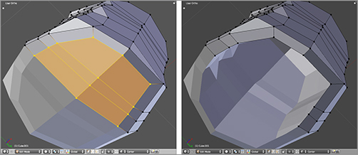
Select the front faces where the eyes will be, extrude once, and then scale down, as shown in . Make two vertical loop cuts as shown in .
Four newly cut edge loops
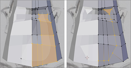
Select the seven faces shown in , and draw the knife tool through them by holding the K key and the left mouse button and moving the mouse across the faces as shown. The result should look like the second image in . Note that the quad in the eye area has been converted into triangles to conform to the newly created geometry. This is fine. Later, you’re going to delete these triangles anyway.
Select the nine faces that make up the front of the nose and mouth area, and extrude and scale them twice, adjusting the location of the vertices to get a result, as shown in . Select the six faces on the bottom of the mesh, and delete them with the X key, as shown in .
Extruding the eye area
Two more loop cuts
Making a cut with the knife tool and the resulting topology
Extruding the nose and mouth area twice
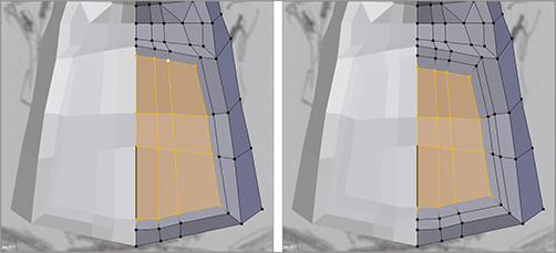
Deleting faces at the bottom of the model
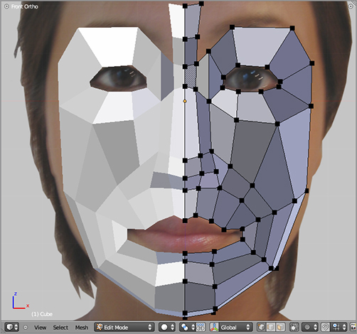
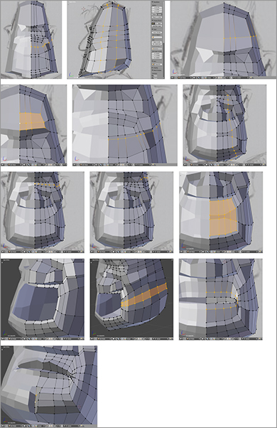
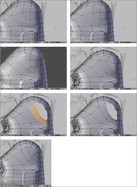
At this point, you should be comfortable enough with the tools to do a little bit of solo flying. Follow the images in to continue modeling the head and face.
Modeling the face with cuts and extrusion
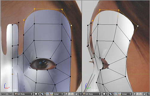
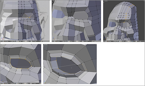
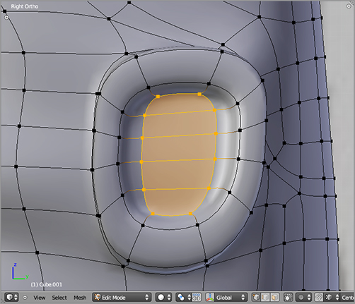
Now you turn your attention to the eye area. You need to reorganize the faces in the eye area slightly by deleting some faces and making some others with the F key. Then you need to make a few cuts and extrude inward to create the eye sockets, as shown in .
Modeling the eyelids and eye sockets
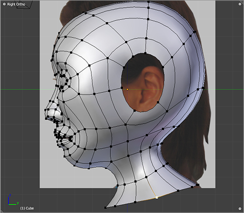
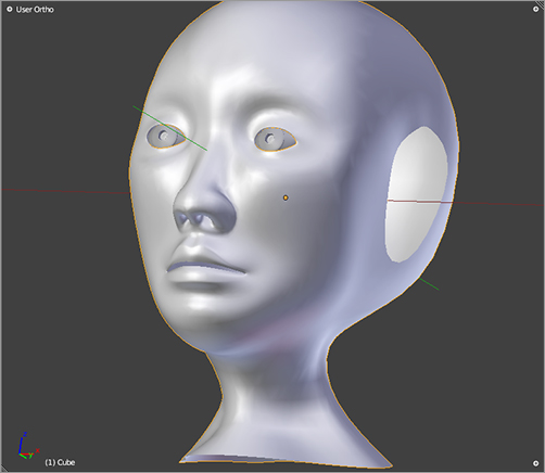
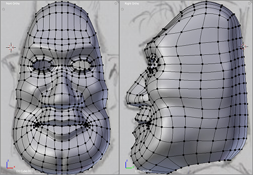
At this point, add a subsurf modifier to get a better sense of how the model will look when it’s finished. The model so far should look something like the one shown in . You can also check what you have against the model in the .blend file for this chapter on the book’s downloadable companion files.
The model so far, with subsurfing
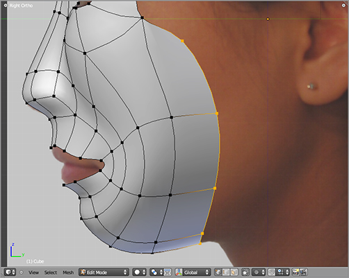
Later, when you add hair to the character, it will be helpful to have the hair-emitting portion of the scalp modeled in an intuitive way. To achieve this, you’ll make some adjustments to the topology of the head. But before that, extrude the basis of the ears as shown in so that you have a better idea of where the hairline should be located.
Extruding the basis of the ear

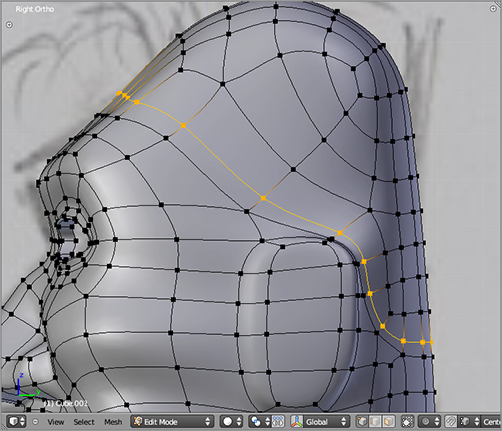
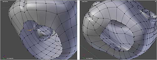
A very handy tool for adjusting the topology of a model is the Rotate Edge tool, which is accessed from the Mesh menu in the 3D viewport header (this menu is present only when a mesh is selected in Edit mode). Select the two vertices shown in , and choose Mesh ⇒ Edge ⇒ Rotate CCW to rotate the edge counterclockwise in the mesh as shown in the figure. Use the Rotate Edge tool again to rotate the edge shown in .
Merge the two vertices shown in into a single vertex. The Merge tool can be found in the mesh Specials menu (W key) or activated directly with Alt+M. Choose At Center when prompted to choose where the vertices should merge. This will merge the vertices at a midpoint between the two original vertices.
Continue in this manner, by rotating edges and merging vertices, to model the hairline into the mesh, as shown in .
Rotating an edge within the mesh
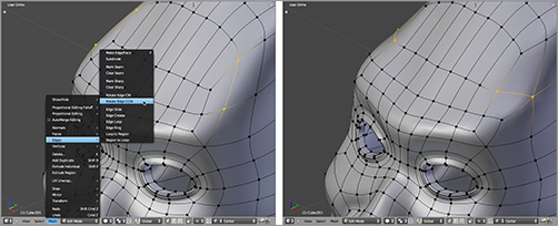
Rotating another edge
Merging two vertices
More edge rotations and vertex merges to create a hairline
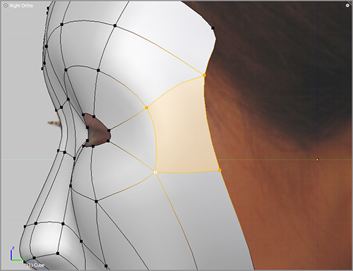
Once you are finished with the basic outline of the hairline, it’s a good idea to clean up the topology of the scalp a bit. Follow the images in to do this. When you’ve finished, add another edge loop around the hairline with the Edge Loop tool (Ctrl+R), as shown in 2.106.
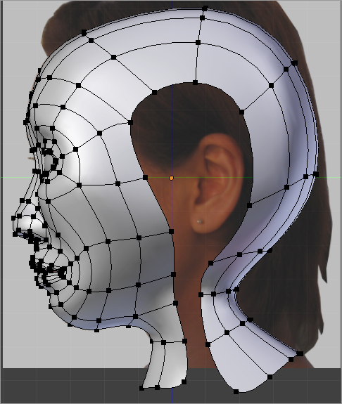
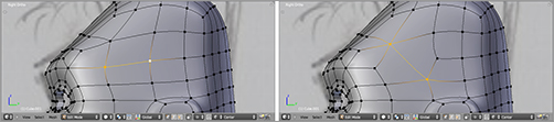
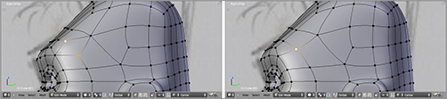
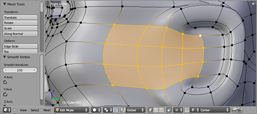
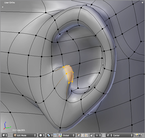
Now you can return to finishing the ear. From the base you extruded previously, extrude, scale, and translate the faces to create a rough ear shape, as shown in . Select the faces shown in , and smooth them using the Smooth tool in the mesh Specials menu (W key). Turn the smoothing iterations up all the way to 100 in the corresponding field in the Tool Shelf, as shown in the figure.
From this basis and with the skills you’ve picked up so far in this chapter, you should be able to use the Extrude tool, and scale, rotate, and translate in order to finish the ear model, as shown in .
Tweaking the topology of the scalp
Adding an edge loop around the scalp area
Extruding more ear geometry
Smoothing the base of the ear
Finishing the ear
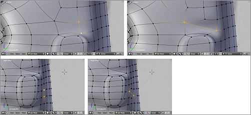
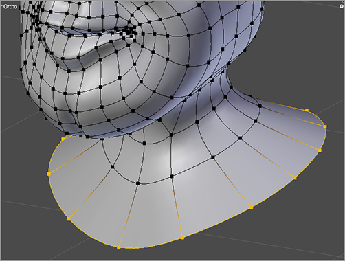
All that is left to do on this model in terms of new geometry is to add a few vertices to the base of the head, as shown in , and to extrude the neck, as shown in .
Adding some faces to the neck area
Extruding the neck
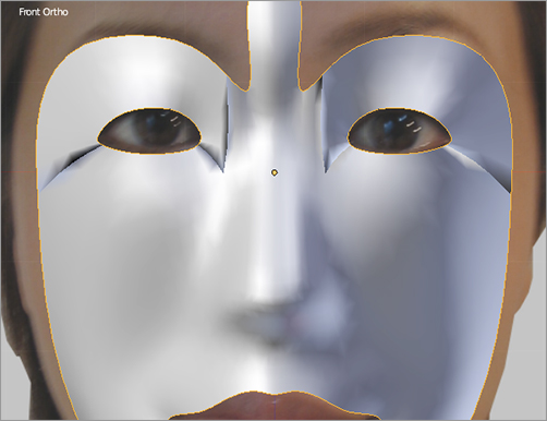
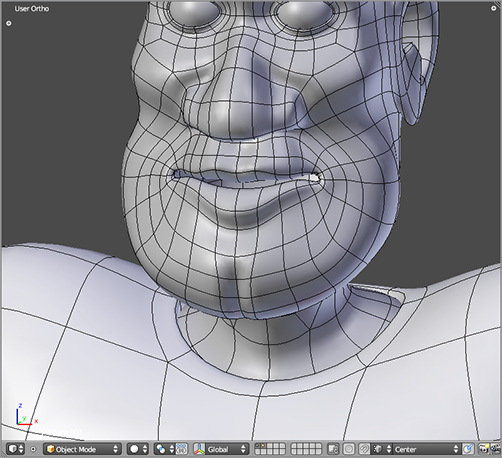
Once you’ve gotten this far, toggle the body visible by holding Shift+clicking the first layer button in Object mode to see how the head and body fit together. Make any necessary adjustments to get them to fit nicely together, as shown in . This is also a good time to add eyes to the model just as you did in the “Poly-by-Poly Modeling and Box Modeling” section of this chapter and to make the necessary adjustments to the shape of the face to accommodate the eyeballs.
For any animation that will involve the character opening its mouth, of course you will also need to have the mouth modeled. This includes the oral cavity, the tongue, and the upper and lower rows of teeth. shows a simple mouth setup that you can use for this character, and shows its placement inside the head. Be sure that it does not poke through the surface of the face.
The head and body together
Modeling the inner mouth
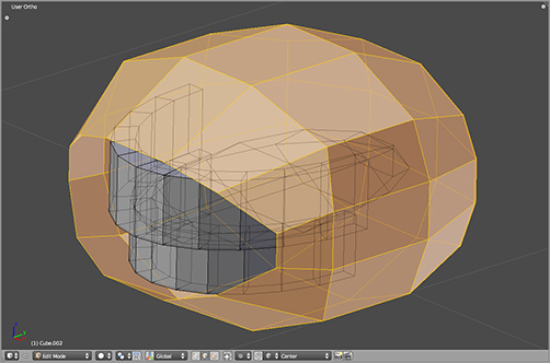
Placement of the inner mouth
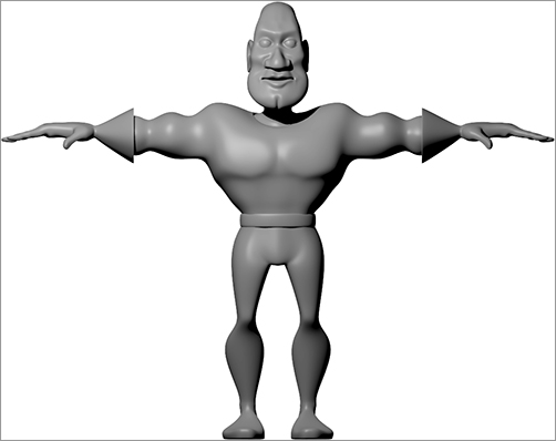
Once you have all this finished, take a break! You’ve finished the complete Captain Blender model, and you’re ready to move on to adding materials and textures to make the model more convincing. shows a simple render of the completed Captain Blender mesh.
The finished Captain Blender model
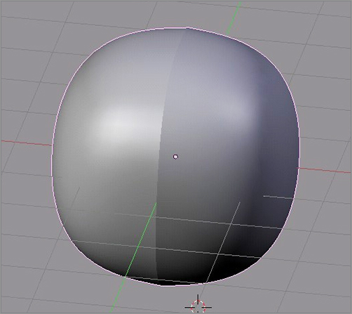
indicates mismatched normals. In the Properties Shelf (press the N key over the 3D viewport) on the Mesh Display panel, you can select to display face normals. If you do this, you can see which direction the normals in your mesh point, as in (normals are displayed in blue by default in Blender). Most often, normals point outward, and in all cases they should be consistent throughout a mesh. In this instance, the normals on the left half of the mesh are pointing outward, as they should be. Because the mesh in the figure is in solid view, you cannot see the normals on the right side because they are reversed and are pointing inward.
This problem is simple to solve. Select all verts, and hit Ctrl+N. The problem should vanish. If it doesn’t, there could be more serious problems with the structure of your mesh.
Inconsistent normals
With Draw Normals turned on, they don’t all point outward.
Overlapping Faces
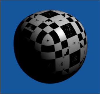
The problem of overlapping faces is often not apparent in the 3D window in Blender; it becomes visible only when the image is rendered, showing up as a pattern of dark artifacts on the surface of the mesh, as in . This problem is caused by multiple faces sharing the same coordinates. It is most often the result of inadvertently duplicating a mesh or portion of a mesh and leaving the duplicated portion in the same spot as the original.
Overlapping faces create artifacts when rendered.
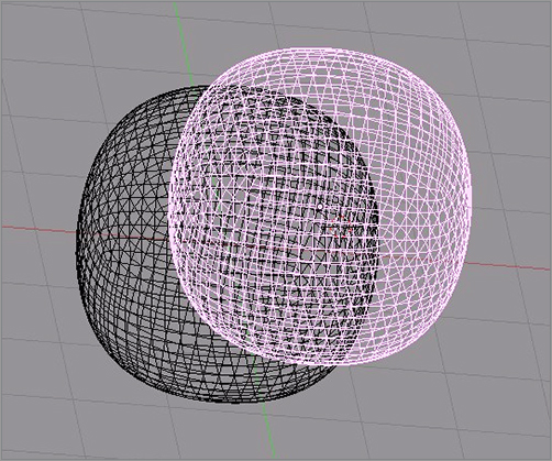
There are two likely possibilities. First, you might have duplicated the object. In Object mode, right-click the Mesh object once, and move it with G to see whether it is a duplicate, as in . If it is a duplicate object, delete the unwanted copy.
If it is not a duplicate object, the verts and faces of the mesh were probably accidentally duplicated in Edit mode. This might show up as a strange pattern of selected edges, as in , but it might also not be evident at all. In any case, the solution is to select all verts in the mesh, press the W key to display the Specials menu, and select Remove Doubles.
Move an object aside to see whether it is hiding an identical object.
A strange selection pattern in Edit mode might indicate overlapping faces.
Internal Faces
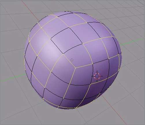
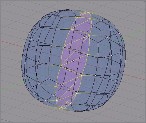
Unwanted pinching in your mesh is often the result of having unnecessary faces connecting parts of the mesh that should not be connected. Generally, a mesh should be hollow, without separate compartments inside it. The pinched mesh in is a result of having internal faces connecting the middle loop of vertices.
A pinched effect caused by internal faces
You can solve this problem by selecting all unwanted internal faces (see ) and deleting them with the X key, choosing Faces from the Delete menu.
Delete unwanted internal faces to solve the problem.
Unwanted Doubles
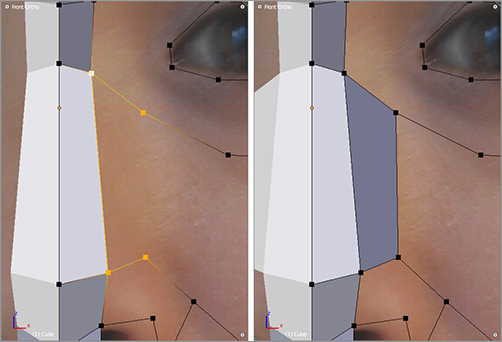
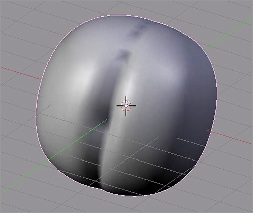
Another common problem is the appearance of a creased seam on your mesh, as in , which is usually caused by doubled edges.
An unwanted crease caused by doubled-up verts
Use the Box Select tool (B) to select the seam, as in , and select Remove Doubles (this can be accessed from the W specials menu). If the vertices are not exactly in the same place, it might be necessary to adjust the Merge Threshold value in the Tool Shelf operator panel when Remove Doubles is carried out. Raising this value increases the area within which verts are considered doubles of each other. Raising this value too high results in merging vertices that should not be merged, so be careful.
Select all verts in the offending area using the Box Select tool.
In some cases, if there is a seam in which the corresponding verts are too far from each other to be merged using remove doubles, it might be necessary to “weld” the seam shut two verts at a time. Select the two verts you want to merge, press W, and choose Merge. You might need to do this for all the verts in the seam in some cases.
Unwanted Extrusions
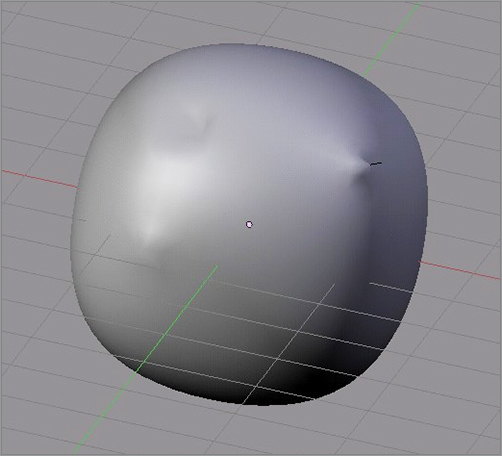
Accidentally pressing Ctrl+LMB with a single vertex selected is a common cause of unwanted extrusions, which can show up in a mesh in a variety of ways, creating pimples and pockmarks on the surface of your mesh, depending on the nature of the extrusion. You can see the surface results of this problem in . The cause of the problem is clearer when the mesh is viewed in wireframe mode, as in .
Problems caused by unwanted extrusion
Unwanted extrusions in wireframe mode
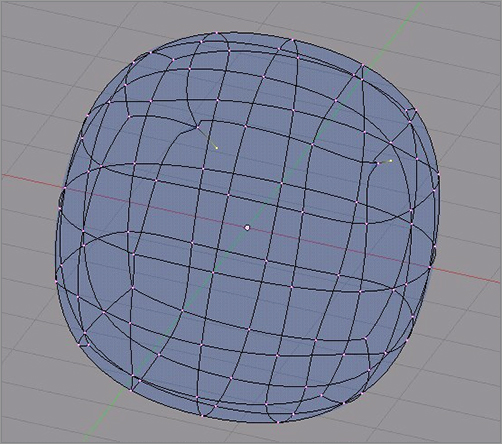
The solution is simply to delete the extruded verts. In the cases in which the verts have been extruded far enough to be clearly identifiable, as in the top two cases where the verts are extruded into and out from the surface of the mesh, the verts can be selected and deleted.
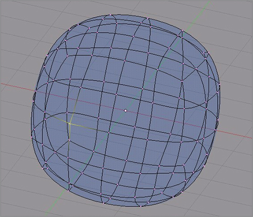
In the more subtle case in , the extruded vert was not displaced and so resides at the same coordinate as the original vert. This is actually just another case of unwanted doubles, and the solution is to select the doubled vert using the Box Select tool and to remove doubles.
A doubled vertex
Now that you understand the basics of mesh modeling and have created the mesh of the character, you can begin to add details. The next chapter will cover creating materials and textures and using static particles to make hair.

