Chapter 1
Blender Basics: Interface and Objects
The first hurdle in learning any complex piece of software is to become familiar with the interface. In the past, this was especially true of Blender, which had until recently garnered a reputation for an idiosyncratic and often perplexing interface. With the release of the long-awaited Blender 2.5, this reputation may change. Blender 2.5 is the result of thousands of hours of designing, debugging, and coding, from a complete recode of Blender’s low-level event-handling system to a top-to-bottom redesign of the graphical user interface (GUI). Users coming from other 3D software will feel especially welcomed by the improved organization of the interface and by its high degree of customizability.
Much of this customizability is the result of an overhaul of Blender’s Python API, which enables advanced users to have near total control over all aspects of the interface (as well as access to most 3D data) via the Python scripting language. For users familiar with the ideas behind object-oriented programming, many aspects of Blender’s organization will be especially intuitive, such as the use of objects, function overloading, and the reuse of datablocks. Getting a good feel for these ideas and how they are implemented in Blender will greatly increase your proficiency at accomplishing what you want. Going further to master Python scripting will give you a great deal of added power over your Blender environment. Nevertheless, it’s not necessary to be a programmer to use Blender, and this book doesn’t assume any programming knowledge.
Blender 2.5’s strengths begin with its interface, and so will this book. Mostly, you’ll learn by doing over the course of this book, but in this chapter, you’ll take a quick look at the most salient points of the Blender interface.
- Work Areas and Window Types
- Navigating the 3D Space
- Objects and Datablocks
- User Preferences
). If it’s not already maximized, maximize it. Blender can use all the screen real estate you can give it.
Blender desktop
You are now looking at your Blender desktop, which should appear a lot like . The Blender desktop consists of a nonoverlapping configuration of windows. By default, the windows are arranged as shown in . As you can see, five windows appear in this configuration. Each window holds a different editor type as identified in the figure. The darker gray areas indicate the placement of each window’s header. Headers can be displayed at the top of a window, at the bottom of the window, or not at all. You’ll see what each editor type is for shortly.
The default window arrangement
You can resize each window by clicking one of the window’s borders and dragging to enlarge or reduce the size of the window, as illustrated in . You can split a window into two identical windows by clicking the upper-right or lower-left corner of the window and dragging in the direction that you want the window to be split, as shown in . You can also merge windows that share a complete border by clicking the upper-right or lower-left corner and dragging across the border that you want to be eliminated, as shown in . In this way, you can arrange the windows on your Blender desktop with a great deal of freedom.
Obviously, splitting a window into two identical windows is of limited use unless you can change the content of the windows, which of course you can. All windows are created equally in Blender; any window can display any editor type. The editor type displayed in a particular window is determined by the icon at the leftmost corner of the window’s header. You can select which editor type is displayed by choosing it from the menu shown in .
Dragging borders to resize windows
Splitting a window into two identical windows
Merging two windows
The Editor Type menu
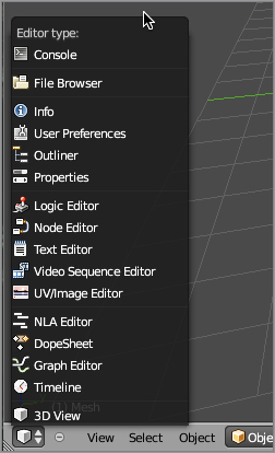
The editor types are as follows:
3D View Displays 3D objects and scenes in various modes, including the Object, Edit, and Pose modes. This editor allows a variety of viewing options, including toggled perspective/orthographic drawing (Numpad 5). The shortcut for accessing the 3D view is Shift+F5.
Timeline Displays the progress through time of an animation. With this editor, you can start, stop, and scrub through the animation, and you can directly input the start, end, and current frames.
Graph Editor Lets you select and edit animation function curves (F-Curves) and drivers. Previous versions of Blender dealt with this functionality by means of Ipo curves, but the old system has been replaced by a more generalized and powerful F-Curve framework. You can access the Graph Editor with Shift+F6.
DopeSheet Provides an organized overall view of an animated scene, enables sequences of armature poses to be stored together as actions for subsequent use in nonlinear animation, and lets you view and edit shape key animations. You can access the DopeSheet with Shift+F12.

NLA Editor Lets you combine actions and other animations in a nonlinear way to form complex animations.
UV/Image Editor Lets you edit UV mapping information and image-based textures. You access the UV/Image Editor with Shift+F10.
Video Sequence Editor Enables nonlinear editing, compositing, and playback of video sequences. It can take still-frame or video sequences as input. You can access the Video Sequence Editor with Shift+F8.

Text Editor Enables text editing. You often use this editor type as an area for notes about the blend file or for Python scripting. You can execute Python scripts from the Text Editor using the Alt+P hotkeys. The shortcut for accessing the Text Editor is Shift+F11.

Node Editor Lets you edit and configure material, texture, and composite nodes. You can access the Node Editor with Shift+F3.
Logic Editor Enables editing of real-time interactive logic for use in the Blender Game Engine. You access the Logic Editor with Shift+F2.
Properties Lets you view and edit property values for a wide variety of contexts and entities including objects, scenes, render contexts, simulations, modifiers, constraints, materials, textures, lamps, and cameras. The Properties window largely replaces the functionality found in the “Buttons area” of older Blender versions. You can access the Properties window with Shift+F7.
Outliner Enables a graphical overview of all datablocks and the links between them, with multiple display options. You can access the Outliner with Shift+F9.
User Preferences Lets you specify look-and-feel preferences, language preferences, file location defaults, and other preferences. You can bring up a pop-up User Preferences window by pressing Ctrl+Alt+U.

Info Provides a header bar with general-purpose menus for file handling, object addition, rendering, help, window configuration, and scene selection. Info also displays diagnostics about scene content and render progress, among other information. The Info window does not contain any functionality other than what is displayed in its header.
File Browser Lets you open files from the hard drive and import or append Blender datablocks from within files on the hard drive.
Console Provides a fully functional Python command-line interpreter with access to the Python API. You can access the console with Shift+F4.
Your operating system may have hotkeys that override the Blender hotkeys. Mac OS X in particular uses the F keys for various desktop management functionality. If you want to use the default Blender keyboard shortcuts, you will need to disable the OS X shortcuts first. See your OS X documentation about how to do this. Some Linux desktops also have built-in hotkeys that need to be disabled for Blender to work right, so please consult the documentation for your system’s desktop manager.
In this book, the term window usually refers to a window with a specific editor type active. For example, the term 3D view window will mean a window with the 3D View editor type selected. It’s perfectly possible to have more than one instance of the same editor type open in separate windows doing different things at the same time. For example, you can have two or more 3D view windows open at once looking at your 3D scene from different directions.
Properties Window
With the Properties editor, you can access a lot of information about many aspects of Blender’s functionality, and as such, it’s a place where you’ll spend a lot of time. The information is fairly dense, so it’s worthwhile to get a general sense of what’s going on there before going much further.
The Properties editor can display any of up to 11 contexts at a time. These contexts correspond to the icons in the header of the Properties window (not all 11 are available at the same time). The possible properties contexts are as follows:
- Render
- Scene
- World
- Object
- Object Constraints
- Modifiers
- Object Data
- Material
- Texture
- Particles
- Physics
Which contexts are available depends on what type of object is selected in the 3D viewport. Throughout the course of this book, you will dip into each of these contexts. In this book, I will usually shorten the terminology by referring to Render properties rather than the Render context of the Properties editor.
Context-Sensitive Menus
Blender contains a number of menus that you can access in certain window types and in specific modes. Throughout this book, you will use these menus to add objects in Object mode, to perform special operations in Edit mode, and to key values for animation, among other things.
). You can position it by clicking where you want it in the 3D viewport.
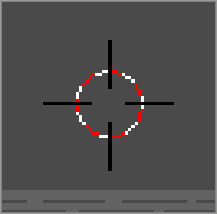
The 3D cursor
Blender Units
Blender uses one unit of measurement, unsurprisingly called a Blender unit (BU). A Blender unit is the size of a single square on the background grid in the Blender 3D viewport. If you are working on scale models, you need to decide what real-world measurement to assign to a single BU and then proportion your work accordingly. Some simulations assume a BU is equal to 1 meter, as does the Metarig functionality that you will see in Chapter 4, so it’s worthwhile to keep this scale in mind, but there’s nothing strict about it. A BU can equal whatever real-world measurement you want. For precision users, Blender 2.5 also has access to metric and imperial unit measurements as well as custom measurement scales.
Using Hotkeys
You will notice that Blender favors the use of a lot of hotkeys. Memorizing and becoming comfortable with the various hotkeys and their specific configurations on your own machine is one of the first hurdles to learning to work with Blender. and list the most important Blender hotkeys. You can configure all Blender hotkeys in the user preferences, but if you plan to use Blender frequently, particularly if you plan to use multiple installations of Blender, then I recommend getting used to the defaults where you can.
Hotkeys common to all modes
| Hotkey | All modes |
| Spacebar | Function search |
| R | Rotate |
| S | Scale |
| G | Translate (move) |
| X | Delete |
| A | Select all/deselect all |
| B | Border select |
| C | Circle select |
| Ctrl+P | Make parent |
| Alt+P | Clear parent |
| Shift+D | Duplicate |
| I | Insert animation key |
| Alt+C | Object conversion menu |
| Right arrow | Move forward one frame |
| Left arrow | Move backward one frame |
| Up arrow | Move forward 10 frames |
| Down arrow | Move backward 10 frames |
| Shift+right arrow | Go to the last frame |
| Shift+left arrow | Go to the first frame |
| 0–9/Alt+0 through Alt+9 | Show corresponding layer |
| F12 | Render |
| F11 | Display rendered image |
| W | Specials menu |
| X, Y, Z | Constrain transformation to (selected global axis) |
| XX, YY, ZZ | Constrain transformation to (selected local axis) |
| Shift+X, Shift+Y, Shift+Z, | Constrain transformation to take place in the selected plane by global coordinates |
| Shift+XX, Shift+YY, Shift+ZZ | Constrain transformation to take place in the selected plane by local coordinates |
| N | Display transform properties |
| Shift+S | Snap menu |
| Numpad 1, 3, 7 | Front, side, and top view |
| Numpad 0 | Camera view |
| Ctrl+Alt+Numpad 0 | Move camera to current view |
| Ctrl+Numeric 0 | Use selected object for camera view |
Hotkeys specific to object and edit modes
| Hotkey | Object mode | Edit mode |
| Tab | Go into Edit mode | Go into Object mode |
| F | Make Edge/Face | |
| P | Play game | Separate mesh selection into new object |
| L | Select linked vertices | |
| M | Move object to new layer | |
| U | Undo | |
| E | Extrude | |
| V | Rip mesh | |
| K | Loop cut/Knife menu | |
| Ctrl+J | Join meshes/curves | |
| Ctrl+A | Apply scale and rotation | |
| Alt+R, Alt+G, Alt+S | Clear rotation, clear translation, clear scale | |
| Ctrl+N | Reload startup file | |
| Make normals consistent; recalculate normals outside | ||
| Ctrl+E | Edges | |
| Alt+S | Fatten/shrink | |
| Ctrl+S | Shear |
You can find information about hotkeys and edit them in the keymap configuration area of the Input tab in the User Preferences window. For users of laptops or one- or two-button mouse devices, some further key combinations are also necessary. The instructions in this book assume you have a three-button mouse and a separate number keypad, but I will point out how to simulate the key combinations if you don’t. With a little time following the instructions in this book, the hotkeys will begin to come naturally, and the speed and ease with which you can work with Blender will greatly increase. If you’ve done animation in other 3D software, you probably have a good idea which of these keys you’ll use most often. If you’re new to the field, expect to become very familiar with the R, S, and G keys for rotating, scaling, and moving things around, as well as with the I key for keying frames for animation.
Layers
In the header of the 3D viewport there are 20 small square buttons, divided into 4 rows of 5 buttons. These buttons toggle the visibility of individual layers in a scene.
Layers let you separate objects in your 3D view so that you can see some objects but not others. The terminology is somewhat arbitrary; layers in Blender are groupings used to hide or show specific objects and to control which objects interact with certain simulations and lighting effects. They can be useful to organize your work during editing and also during animation. You can restrict lights to illuminate only objects on the same layer as the light, which is an indispensable tool in lighting. Also, you can limit forces such as wind effects, curve guides, and collision effects (discussed later in this book) to affect only those objects on their own layer.
You can toggle the layers that are visible in the 3D viewport and to the renderer by using the buttons mentioned previously or by using the keyboard number keys (not the numeric keypad). You can toggle multiple layers at once by Shift+clicking the buttons. The top row of layers corresponds to the keyboard number keys 1 through 0. The bottom row of layers corresponds to Alt+1 through Alt+0. In general, you use the numeric keypad to change views, and you use the keyboard numbers to change layers. You can use either to input numbers into a text field, for example.
If you accidentally press a keyboard number key other than the layer you are working in, it may be a shock when all the objects suddenly disappear from the 3D view window! Don’t panic; simply return to viewing the layer your work was on by using the layer buttons.
You can send an object to a different layer by selecting the object and pressing the M key. A dialog box displays with the layer buttons in the same order as they appear in the 3D viewport header. Simply click the layers you want to send the item to, holding Shift to select multiple layers, and click OK. An object can reside on as many layers as you choose.
Views and Perspective
There are various ways to view your scene. When you open Blender initially, default view shows the scene in perspective view, in which lengths and sizes are affected by their distance from the viewer and things farther away appear smaller, just as in nature. To toggle into orthographic mode, press 5 on the numeric keypad. This mode gives a less realistic orthographic view that can be easier to work with.
It is possible to zoom too far forward in perspective view and find yourself trapped. If your viewpoint seems frozen or difficult to control, this is probably the problem. Simply press 5 on the numeric keypad to toggle into orthographic view, and then zoom your viewpoint out. You can also press the Home key to bring the entire scene into view.
Using the number pad, you can switch your view to follow the x-, y-, or z-axis. The numeric 1 key changes the view to look down the y-axis (front view), and numeric 3 will change the view to follow the x-axis (right view). Holding down the Ctrl key while you press these numbers changes the view to their respective opposites, looking up the axis from the negative direction. Numeric 2 and 8 rotate the scene vertically with respect to the 3D viewport, and numeric 4 and 6 rotate the scene horizontally.
If you use a laptop without a numeric keypad, setting the Emulate Numpad user preference will let you switch views using the ordinary keyboard numbers. If you select this, the keyboard numbers will no longer switch visible layers. I rarely if ever use keyboard numbers to set layer visibility, so I always choose this option.
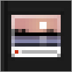
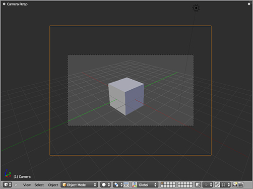
The 0 key on the numeric pad switches to the active camera viewpoint. A dotted rectangle frames the view, indicating the video-safe area, as you can see in . If the camera is on a visible layer, a solid rectangle also appears, representing the camera. You can right-click this rectangle to select the camera, like any other object. From other views, you can place the camera at the current view by pressing Ctrl+Alt+Numeric 0, which will also put you automatically into camera view. You can also use Ctrl+Numeric 0 to place any object in the active camera. You can use this shortcut to switch cameras, but you can also use it to check on the viewpoint of other objects, which can be useful for directional objects such as spotlights.
Camera view
Interacting with 3D Objects
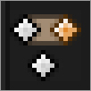
In the header bar of the 3D view window, there is a drop-down menu for selecting the mode. The default mode to begin with is Object mode, in which you can select and manipulate objects and relationships between them.
You can select objects in several ways. The simplest way to select a single object is by right-clicking it. If you hold Shift, you can add individual objects to the selection. Selected objects are outlined in shades of orange. The last object you selected is outlined in a lighter orange, indicating that it is active. To make one of the other selected objects the currently active object, Shift+right-click it. Shift+right-click the active object to remove it from the selection. By pressing the Z key, you can toggle between the wireframe and solid views. In solid view, you cannot select objects that are completely obscured from the view by other objects. You must either move your view to a place where you can get to the object or enter wireframe view. Alt+right-clicking a spot with more than one selectable object lets you select from a list of those objects.
You can also select objects with the Box Select tool, accessed by pressing the B key once. With this tool, you drag a box over an area of the screen and then select all visible objects within the box. Hold down the left mouse button while dragging the box to cover the selection. Pressing the B key and then dragging the box with the middle mouse button uses the box for deselection. There are several ways to manipulate the location, rotation, and size of objects, and it is entirely a matter of personal preference which one to use.
Hotkeys
The following are some hotkeys that might be helpful:
- To rotate, press the R key once, and rotate the object with the mouse. The default rotation axis is the current angle of the 3D view. After you rotate the object the way you like it with the mouse, click to accept the new rotation; otherwise, right-click to quit the rotation without making the change.
- To translate or change an object’s location in 3D space, the hotkey is G (for “grab”). Press this key once, and move the object around with the mouse. As with rotation, clicking finalizes the move, and right-clicking aborts it.
- To scale an object, the hotkey is S. When you have pressed the S key, moving the mouse closer to the pivot point reduces the scale of the object, and moving the mouse farther from the pivot point enlarges the object. Again, clicking finalizes; right-clicking aborts.
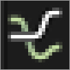
Motion Manipulators
Blender also provides the manipulator widgets shown in for rotating, translating, and scaling. You can toggle these three manipulators on and off independently of each other by using the buttons in . To use a manipulator, click the colored portion of the manipulator of the axis along which you want to perform the operation. In the case of translation, click the colored arrow on the appropriate axis; in the case of scaling, click the colored rectangle; in the case of rotation, click the colored curve that circles the axis you want to rotate the object around.
The manipulator widgets: (a) rotation, (b) translation, (c) scale
The manipulator selection buttons

Restricting to Axes
When you rotate, translate, or scale, you often want to restrict the operation to a particular axis or to fix one axis while operating in the other two. To select an axis to rotate, scale, or translate along, press X, Y, or Z after pressing the R, S, or G key. This restricts the operation to the global axis. Press the axis key twice to restrict the operation along the object’s local corresponding axis. To scale or translate along a plane, press Shift and the key corresponding to the axis you do not want changed. For example, to scale an object along its x- and y-axes, press S followed by Shift+Z.
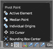
Pivot Point
The pivot point is the point around which rotations are calculated, and it is also used as a reference point for scaling. You can choose the point to use as your reference point in the drop-down menu shown in . The default, Median Point, is a point calculated to be in the center of your entire selection. If you have multiple objects selected, the median point is somewhere in between them all. You can choose to have objects rotate independently around their own centers, around the active object, around the 3D cursor, or around the center of the object’s bounding box. The default median point pivot, which you can set with the Shift+comma hotkey, is the most commonly used, but in this book you will occasionally switch the pivot point to be the 3D cursor for specific purposes, which you can set with the keyboard period key.
Pivot selection drop-down menu
Object Centers
Every object has a center. The center is the point around which the object rotates by default, and the location of the center is considered to be the location of the object. When you translate and rotate in Object mode, the actions are carried out on the entire object. However, in Edit mode, you can move the 3D portion of the object (for example, in the case of a Mesh object, by selecting and moving the entire mesh in Edit mode) without moving the center. When you do a lot of editing, this can easily happen and cause poorly placed centers that can cause unexpected behavior with objects. You can set the origin either by using the Tool Shelf button or by using the hotkey Shift+Ctrl+Alt+C over the 3D viewport region, which will open a menu of options for setting the origin.
Parenting
Parenting is an important way to create relationships between objects (and some other entities). You will use parenting often in modeling, animating, and texturing. When one object is parented to another, you can refer to the first object as the child and the second object as the parent. In this case, the child object’s movements are all considered only in relation to the parent. When you translate, rotate, or scale the parent object, you do the same to the child object. However, the relationship is not symmetrical. Like a moon around a planet, the child object can move or rotate in relation to the parent object without influencing the parent object. To define a parent relationship, select more than one object. The active object is the last object selected, and by default it is highlighted with a lighter orange than the previously selected objects. Press Ctrl+P to parent all selected objects to the active object; that is to say, the selected objects all become child objects to the active object. Put another way, the object you selected last will become the parent of the other objects. In the case of two objects, the first object you select is parented to the second object. To delete a parent relationship, select the objects and press Alt+P to open a menu of options for clearing parent relations.
Parenting is not restricted to just object/object relationships. Vertices or bones can be parents to objects. There are two types of vertex parenting: single-vertex parenting and triple-vertex parenting. With single-vertex parenting, the parented object follows only the location of the parent vertex. Triple-vertex parenting allows the object to follow both the location and the rotation of the vertex triad to which it is parented. You will see an example of vertex parenting in Chapter 3.
Similarly, bone parenting allows an object to be in a parent relationship with a single bone in an armature. In bone parenting, the parented object inherits the location, rotation, and other qualities (such as squash and stretch) from the parent bone. You will see examples of bone parenting in Chapter 4.
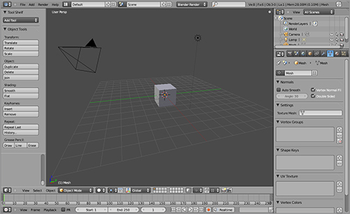
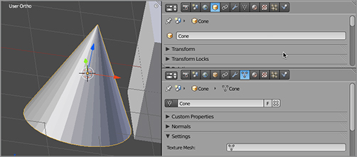
. The highlighted fields in that figure indicate the object name and the name of the Mesh datablock. They both read Cube. Because objects and datablocks have separate namespaces, it is not a problem for them to be named identically; in fact, most of the time, it is intuitive, so they should be named identically.
Viewing object properties and object data properties
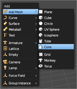
Now, in Object mode, click to place your 3D cursor off to one side of the default cube, press Shift+A to open the Add menu, and add a cone mesh, as shown in . Select the Cap Ends option in the Tool Shelf when adding the cone so that the cone is a closed solid mesh. Note that the mesh name and the object name, predictably enough, are Cone, as you can see in . (If you add another object of the same type, Blender automatically appends the suffix .001 to the end of the new name and increments for each subsequent new object.)
The Add menu (Shift+A)
Select the Cube Mesh object by right-clicking it. Click the small triangle mesh icon to the left of the datablock’s name in the Object Data’s Properties window, as shown in ; a drop-down menu appears with the available mesh names. In the drop-down menu, Cone will be an option. Select this option, and your Cube object is now a cone! Not only is it a cone, but it’s the same cone as the Cone object. If you edit the mesh on one of these objects, both objects’ meshes will be edited, as you can see in .
The object and datablock names visible in the Properties windows
The datablock name drop-down menu
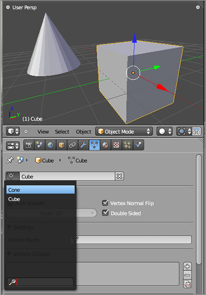
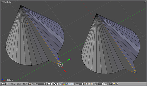
Although the mesh data is identical, the objects are still very much independent. To see this, in Object mode, select the Cube object. Press S, and scale the object to about twice its size. Now you have a big cone and a small cone. This is because mesh edits are made to the Mesh datablock, which is now shared between the objects, whereas the overall scale is an object-level property. Go back to the mesh drop-down menu on the Cube object and look at the options.
In the drop-down menu, there are two options: Cone and Cube. Select the Cube mesh from the drop-down menu. Now your Cube object is again associated with a Cube mesh. However, the cube is now twice the size that it was before because the scaling you did in Object mode applied to the object instead of the mesh.
Exploiting this distinction between Mesh objects and the meshes themselves can be very useful for character animation because it helps maintain a flexible and modular workflow. An armature modifier, as you will see later in the book, operates on a Mesh object, which means you can replace the mesh in the middle of an animation simply by swapping a new Mesh datablock in as the object data for the animated object.
You will learn more about these meshes in Chapter 2, so it is a good idea to save this .blend file now so that you can return to it later.
Editing the mesh
Managing Datablocks
Datablocks describe most aspects of modeling and animation in Blender. Materials, textures, Ipo curves, and actions are all examples of datablocks that can be freely associated with any number of different objects after they’re created (see ).
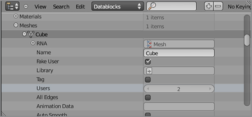
(a) The default Cube mesh has one user, the Cube object. If it is unlinked from this object, it is not persisted after the file is closed because it has no users. (b) By toggling the F button, a fake user is added (the 2 refers to the number of users for that datablock). Now, even if there are no real users of the datablock, it persists because its user count is not zero.
In the preceding example, the Cube mesh datablock is no longer associated with any object. Blender discards unused datablocks when it shuts down, so if you save the file and then shut down and restart Blender with things in that state, this mesh is gone. In fact, there is no way to actively delete such datablocks; they remain “alive” until Blender quits. If you want to purge unused datablocks without completely quitting Blender, you can save and then reopen your file.
Sometimes, you want to keep a datablock on hand even though it does not have a user object. If you want an unused datablock to persist after saving, you must create a fake user for it. For datablocks that can be retained in this way, including the ones mentioned previously, there is be a button next to the datablock drop-down menu with the letter F, as shown in . Selecting the datablock you want to make persistent and clicking F creates a fake user for the datablock so that it will not be discarded at shutdown.
Outliner Window
In some cases, such as actions, Blender creates a fake user automatically when the datablock is created. In this case, you may want to remove a fake user to delete the undesired datablock. To do this, you use the Outliner window in Datablocks view. Datablocks are organized by type. You can navigate to the datablock you want to toggle and choose whether it should have a fake user using the appropriate check box. shows the check box for the Cube mesh in the Datablocks view of the Outliner. In many cases, an F icon is shown beside mentions of a datablock. In these cases, you can remove fake users by clicking the F icon.
Datablocks view in the Outliner window
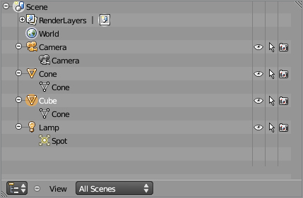
The Outliner window also provides several other organized views of the data in your .blend file. By default, it opens with the All Scenes view selected, as shown in , but you can select from different types of information to view using the drop-down menu.
To the right of each 3D object in the scene view are three icons: an eye, an arrow, and a camera. The eye icon toggles visibility of the object in the 3D viewport. The arrow icon toggles selectability in the 3D viewport. The camera icon toggles whether the object will be rendered.
The Outliner window displaying all scene information
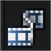
Accessing Data from Different Files
You often need access to objects or datablocks from other files. Animation projects can quickly get far too big to store in single .blend files, and yet many different scenes and shots may share the same main elements. You can access datablocks between separate files in Blender in several ways.
The first and simplest way is to use append. To append a datablock from another file, select Append from the File menu or press Shift+F1. A File Browser window opens, in which you can access .blend files stored on your computer and their contents. In the File Browser window, when you click the name of a .blend file, you see a list of datablock types, just as if they were directories. Enter the appropriate type directory; you see a list of the datablocks of that type available for appending. Here is another place to be aware of the difference between objects and object type datablocks. If you want to append a Mesh object from another file, for example, you find the object in the Object type directory instead of the Mesh type directory.
Another approach to using data across separate files is by linking the datablocks. Linking can be done similarly to appending, except that in the File Browser header, the Link button is selected instead of Append and the Tool Shelf area to the left of the browser contains options related to linking. In this case, the data can be edited only in the file from which it was originally linked, and all edits appear in the files that linked to the data. The hotkey for linking is Ctrl+Alt+O.
Groups
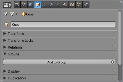
Objects can be collected together into named groups using the Add To Group button in the Object Properties area, as shown in . Groups themselves can then be treated as an object type when appending, allowing you to append whole collections of objects easily.
Add To Group button
.
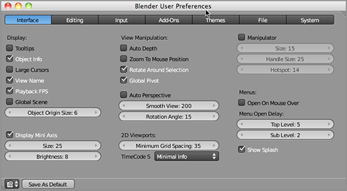
Interface Gives you options related to Blender’s GUI and interaction with the 3D space. Some of these options are self-explanatory, and they are all a matter of taste, so experiment with different settings. I recommend you check the Rotate Around Selection option, particularly if you plan to do mesh modeling. This ensures that whatever you are working on stays centered on your screen when you rotate the space.
The User Preferences window
Editing Presents options for editing objects, animation curves, grease pencil sketches, and other kinds of editing. Settings for the Undo feature are also accessed in this panel. You can adjust these settings to save memory, but I recommend keeping your undo steps as high as your resources allow.
Input Presents options related to user input. You can find the options for Emulate 3 Button Mouse and Emulate Numpad in this panel. You can switch between trackball and turntable orbit styles for rotating the 3D space. Blender’s default setting is Trackball, which can be disorienting for users of other 3D software that uses the more constrained turntable style of 3D orbiting.
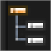
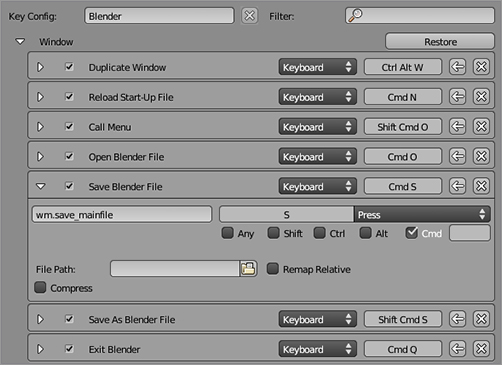
This panel is also where you can set your preferences for hotkey combinations. The hotkeys are organized in a functionality-based tree structure. You can access the hotkey settings for each area of functionality by clicking the triangle next to the functionality label to reveal the full list of hotkeys related to that functionality. shows the hotkey settings for saving a Blender file revealed under the Window functionality list. The default hotkey for saving is Ctrl+S. As you can see in the figure, both the pressed key and the help keys can be edited in this panel, as well as some options specific to the functionality. In addition, the Python call related to this function is also shown, making this panel a handy quick reference for scripters also.
Add-Ons Enables you to select which add-ons will be available in your Blender environment. Add-ons provide additional functionality coded in Python, and they integrate seamlessly into the Blender interface. For example, some mesh add-ons provide a selection of additional mesh primitives available through the Add menu.
Themes Enables you to tweak the colors and some other properties of visual elements of Blender. The visual elements of all editor types can be adjusted in this way.
Editing the hotkey combination for saving a Blender file
File Enables access to file-related preferences including default file paths and options for how many backup versions to save and how often to autosave.
System Gives you access to some miscellaneous preferences such as sound-handling preferences, OpenGL lighting and clipping in the 3D window, the color picker type, custom weight paint range, and lower-level operating-system-related preferences. As a new Blender user, you will probably not have much cause to vary these settings from the defaults.
After you have the configuration the way you like it, press Ctrl+U or click Save As Default at the bottom of the User Preferences window. When you do this, the entire current state of Blender (except for the User Preferences window itself) will be saved as the default state when you open Blender. This means any model or scene in your 3D viewport will also be loaded as the default state of Blender. To return your start state to the original default, choose File ⇒ Load Factory Settings in the Info header. You can save that state again by pressing Ctrl+U.
You should experiment with user options. There’s a lot to play around with, in terms of look and feel. As long as you don’t press Ctrl+U, all settings will return to their defaults on your next startup. For the rest of this book, we assume most things to be in their default configuration, and the figures will all show the default theme.
Now that you’ve looked at the basics of the Blender interface and the datablock system, you’re ready to get your hands dirty and begin modeling.

