Chapter 4: Input Nodes (I)
The input nodes let you use a lot of different methods to distribute effects across your objects. They are very powerful and in some case largely unknown.
Texture Coordinate (T)
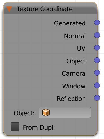
This node is typically used to determine the mapping of textures onto your object.
It has the following outputs:
Generated
Blender automatically generates the coordinates for you. The calculation is based on the bounding box of the mesh before it is deformed by modifiers. The origin is at the bottom left corner of the bounding box. This will usually generate more consistent results when animating.
Normal
The normal vector of the object surface is used as coordinate. Useful for effects that depend on viewing angle.
These are the o bject space normals, so textures stay fixed on the object as it is transformed. As opposed to the normal output of the .
UV
UVs have to be defined by the user and are the most commonly used method for texturing complex objects. In short: the process of manually defining how a 2D image is projected onto a 3D object is called UV unwrapping. The U stands for the X axis of the image and V for its Y axis, just so they will not be confused with the X and Y of 3D space.
Trivia :
The coordinates are called U, V (and W) because those are the three letters before X, Y and Z in the alphabet. The latter were already taken for coordinates of vertices/objects in 3D space. There is another use of the UVW coordinates of an object that takes into account its local transformation, see .
Object (vector out)
This option works similar to generated coordinates, but the origin point is the object’s origin and the texture does not get stretched by the dimensions of the bounding box. It does get stretched from scaling in object mode, though.
Hint: you can use it to texture hair, not along the strand, but across the surface.
Camera
Textures distributed by this method will stick to camera, even if the object, the texture is applied to, moves. Objects moving while the camera doesn't will have the texture dragged across them. The origin is at the position of the camera, meaning in the center of the rendered image. Values left of the center are negative. Also this projection method is dependent on the distance of each shading point to the camera. An image projected onto a plane with this method will appear four times, once in each quadrant of the coordinate system.
Window
The texture will be stuck to the screen, or more precisely: The editor window. A gradient for example will start on the left and go to the right. This means the X value is 0.0 on the left and 1.0 on the right, while the Y axis originates at the bottom and will be 1.0 at the top. This means an image projected by this this method will stick to the screen, no matter how the camera or objects move.
Note: If you are using 3D Viewport (preview) rendering, the projection will not be dependent on your camera position, but rather on the frame of your entire viewport, so differences between preview and render can occur .
Reflection
This input is commonly used to fake real reflections, e.g. if you only want an environment to be seen in the reflections, but not other objects. You can think of it as a texture wrapped around a sphere, surrounding the object and then being seen by the camera as the resulting real reflection.
Note: This input method is more commonly used in games and rasterizing renderers, since it computes a lot faster there.
Object (drop down slot)
If you select any object other than the one using the current material the output of the object (vector out) changes to take the selected object as the source. The texture behaves in the same way as described above, but relative to the input object. This means in the case of a second object used as the input transformations in Object mode of the second object will have an effect on the texture space and the origin of the texture will be at the origin of the selected object.
From Dupli
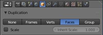
For this setting the object the material is assigned to must be duplicated by the vertices, faces or particles of a parent object. If said parent object uses a texture, each dupli object will receive the color of the pixel it sits on top of. So each copy will receive only one color dependent on the texture and UV map of the parent object.
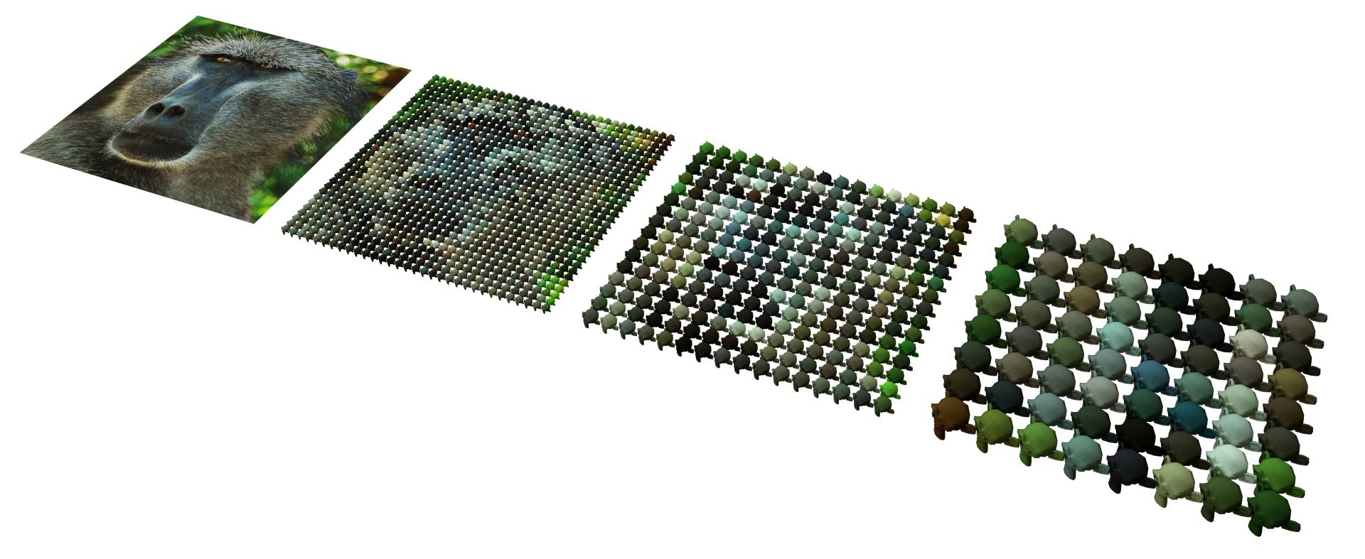
Fig. 4.1) Example of the from dupli -effect. On the left a plane with image texture. The other three planes used monkey heads as dupli objects. The more often the plane got subdivided, the more and thereby smaller monkeys appeared on its surface. Each object is uniformly colored by the color the texture has at the very spot the object is located.
Attribute (A)
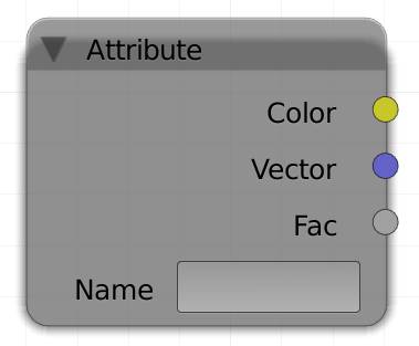
If there is an input without an individual node for it, you'll have to use the attribute node. You can use it for:
1. Vertex Color
Vertex colors are color information stored in the vertices of a mesh. You can extract the vertex paint/colors of your object. Some exporters will use vertex paint for colored objects, as it does not rely on UV coordinates and Blender allows you to paint on vertex colors as well. To use a specific vertex color layer type its name into the name field of the attribute node. If you input vertex colors, you can also use the factor output to extract their values (desaturating the colors).
In case there is a UV map with the same name as a vertex color layer, the UV map will be used.
2. Fire and smoke
The smoke simulator has a fire as well as a smoke output for Cycles. To use their results in the attribute node, simply type flame , density or color respectively into the name field.
3. An additional set of UV coordinates, since the UV output of the node will use the map that has the camera enabled in the data tab of the properties panel. To use a specific UV map, type its name into the name field. Since 2.71 there is a node dedicated to UV input: .
Also other attributes like position (P), normal (N), geometric normal (Ng) may be accessed this way, if you type in the letters in parenthesis. But just like the UV map there are more convenient nodes for this, like the .
Further attributes you can access: generated (also available from the node), pointiness (also available from the ) and tangent (a set to UV will produce the same output).
You might have noticed that there are three outputs, but only one type of input: a string (text). Cycles will automatically recognize which kind of output to utilize from the text entered.
If you want to use UVs, use the vector (blue) output. Vertex colors will be output in the color (yellow) and fire / smoke will influence the factor.
Name
Type in the name of the attribute you want to use here. Possible attributes are flame, density, color and vertex color names.
Color
In case your input supports color information use this output (e.g. vertex color).
Vector
In case your input is a vector, use this output (e.g. UV map).
Fac
In case your input is supposed to provide a factor, use this output (e.g. flame, density). Also useful to output color data as grayscale (e.g. a vertex color layer).
Light P ath (L)
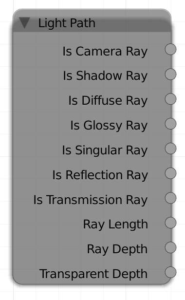
Rays of light traveling through the scene have different types. They all start of as camera rays, since they originate from the camera. If a ray hits a surface, it is converted or split into a different type. For example if a ray gets reflected off a glossy surface it becomes a glossy ray.
The light paths can be used for surfaces as well as lamps. If, for example, you want to emphasize caustics behind an object made of glass, you can add in an emission shader with a higher value for transmission ray to the lamp.
The “Is” in front of a value indicates that a value is either one or zero (white or black), nothing in between. So if you want to alter the strength of emission for a certain type, you can use a math multiply node in between the light path and the strength socket of your emission shader. There are numerous uses for the light path node, e.g. an emission shader can be turned into a shadeless material by plugging is camera ray into the strength input of the emission shader.
Is Camera Ray
All rays are camera rays until they hit any kind of surface or volume.
An object with an emission shader and camera ray as strength input will be shadeless and its emission will not effect the objects around it.
Is Shadow Ray
are special additional rays that are cast at each bounce towards a random light source. They are blocked by all surfaces except for transparent shaders.
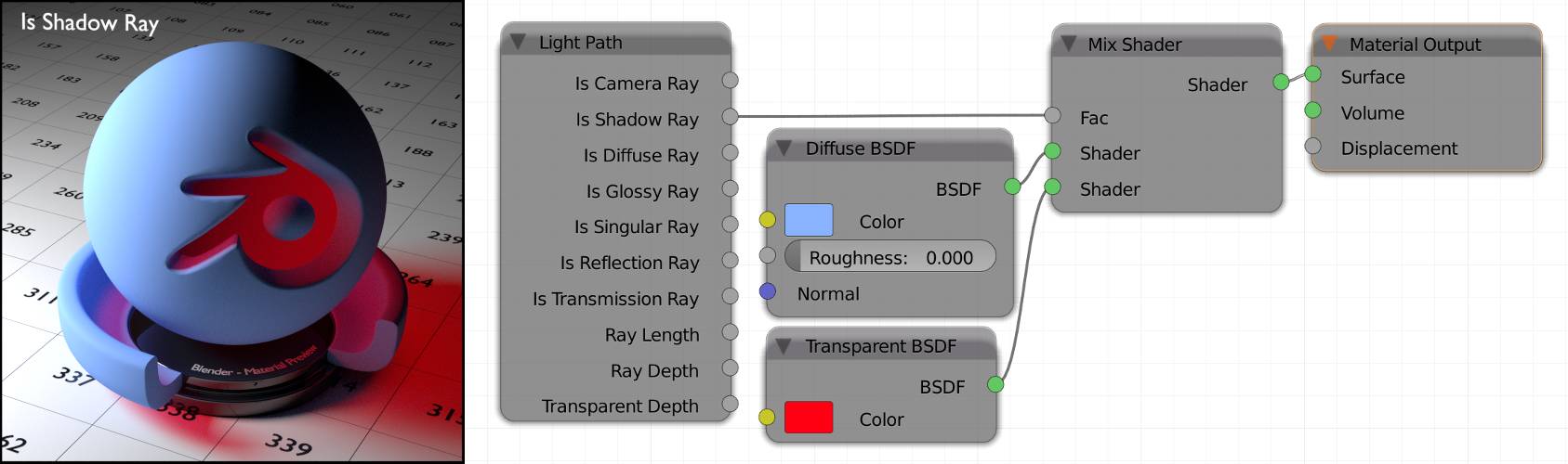
Fig. 4.2) Example object with one area lamp to the left. A red transparent shader is mixed with a diffuse shader with Is Shadow Ray as the factor. This way areas where the shadow of the object was cast were tinted red because normal rays get blocked while for shadow rays the object is now transparent with a red tint. Note that the top right of the object is dark, but not red. That is because rays hitting that area are scattered away from the light source completely.
Is Diffuse Ray
When a ray hits a surface with a diffuse shader, it becomes a diffuse ray (this is also the case for the set to diffuse and the ).
Is Glossy Ray
When a ray hits a surface with a glossy shader, it becomes a glossy ray (this is also the case for the set to glossy, the , the set to reflection and the reflective component of the ).
Is Singular Ray
A singular ray is a ray that only had one possible path to travel but is not a camera ray. This applies to all rays that have hit a shader set to sharp . In that case the ray will continue as singular. The sharp setting is only available for , and BSDFs. This also applies to the aforementioned shaders when roughness is set to 0.0. A ray from a shader set to sharp is always singular, even when it’s path had a random element before (e.g. a ray hitting a diffuse surface first and then a sharp glossy one will continue as singular).
Is Reflection Ray
All shaders that reflect light result in reflection rays. That includes all shaders listed in sections for Is Diffuse Ray and Is Glossy Ray. Which also means that all diffuse rays and glossy rays also carry the reflection ray tag.
Is Transmission Ray
Rays traveling through an object become transmission rays for the following shaders: , and BSDF. The BSDF does not produce transmission rays, instead it will increase the transparent depth .
The other options are:
Ray Length
How far a ray has traveled since the last bounce, measured in BUs.
Ray Depth
Every bounce of a light ray will increase its depth. So before it has hit any object, its depth will be zero, every time it hits a surface its depth will be increased by one. You can use this option to control very precisely which bounces you want to be rendered.
Transparent Depth
Counts how many times a light ray has passed through a transparent shader. It is very useful when you have a tree with lots of leafs with a leaf texture with alpha channel. Using this option, you can limit the number of times the alpha channel is rendered transparent, saving bounces and thus render time.
Fresnel (F)
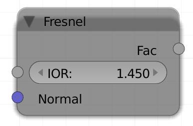
This node generates a grayscale map that represents the Fresnel effect.
Augustin Jean Fresnel discovered in 1822 that the glossy and transparent mix of a surface like water depends on the angle of which you look at it. This way when you look straight down at a water surface, you can see straight through it, as the angle decreases, the surface will act more and more like a mirror. You can see this effect in action when you look at a lake. In the foreground you will see the bottom, while in the distance the environment gets reflected. This effect can also be used on non-reflective surfaces, depending on the directions of the normals in relation to the camera, normals that point further away from the camera become more and more white with this node.
Hint : This node can also be used to simulate a rim that you get from backlighting effects.
IOR
The index of refraction basically determines how sharp or soft the transition from bright to dark is in the resulting map. Higher values make it softer.
Normal
You can provide this node with a normal map, so the simulated displacement of your material is also taken into account by the layer weight, rather than applying it to the shaders after the effect has been calculated.
Fac
This node will not output any color variations, but rather a grayscale map.
Hint: Use this as an factor in a color mix node to colorize the output.
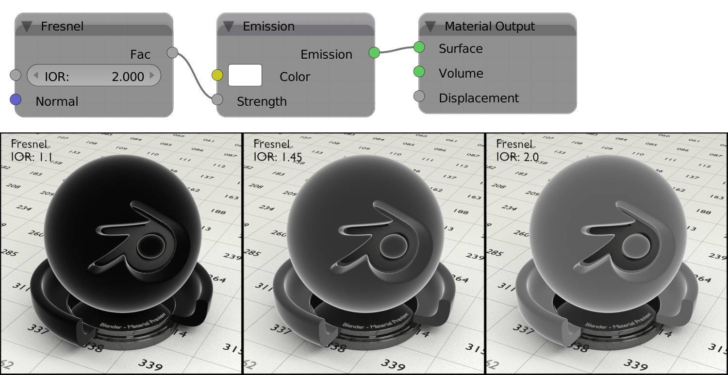
Fig. 4.3) Fresnel visualized by plugging the Fac output into the strength input of an emission shader (node setup above). IORs from left to right: 1.1 (1.0 would be completely black), 1.45 (the default) and 2.0.
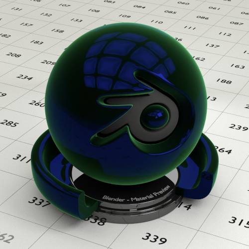
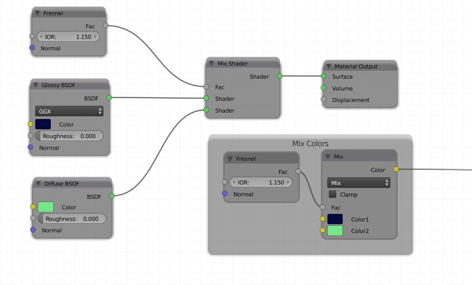
Fig. 4.5) Node setup for mixing a glossy with a diffuse shader by a Fresnel factor. The IOR of the Fresnel node was set very low. In actual scenes, you might want the effect to be more subtle. This setup delivers much more realistic results than just mixing shaders by a factor. If you want to use the Fresnel effect on a single shader, you can also just mix two colors with the factor (mix colors frame).
Layer Weight (W)
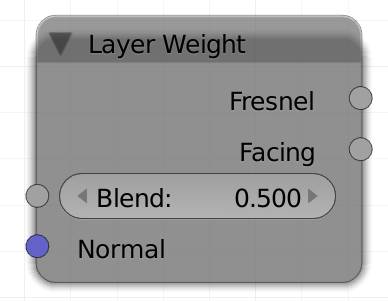
There are two out sockets on this node, which do a similar thing. They will highlight the rim of your objects. Which part of your object counts as a rim is determined by the direction of the of the faces in relation to the camera. Faces with normals closer to 90° to the viewing angle will be brightened with this node.
Blend
The node comes with a blend slider, which lets you control the transition between the two extremes. High values make the effect more subtle, whereas low values increase the contrast. A value of 0 returns only black, 1 returns white for the entire surface.
Normal
You can provide this node with a normal map, so the simulated displacement of your material is also taken into account by the layer weight, rather than applying it to the shaders after the effect has been calculated.
Fresnel
This is similar to the effect of the , but instead of an IOR input, you get a blend factor to control the smoothness of the effect. The conversion between blend factor and IOR works as follows:
IOR = 1 / (1 - Blend)
Blend = 1 - 1 / IOR
Facing
Depending on the normals’ direction towards the camera faces get colored black (towards) or white (away). As opposed to the Fresnel factor, the interpolation between normals pointing towards the camera or away from it is linear.
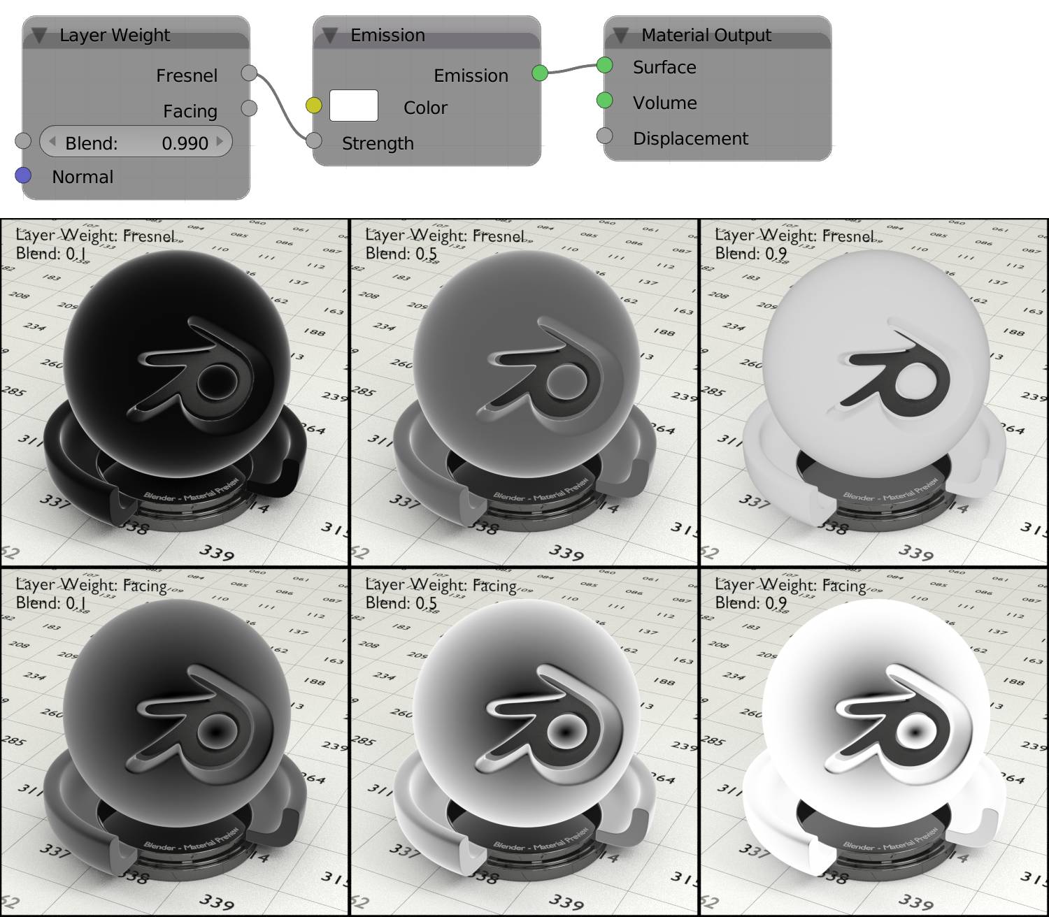
Fig. 4.6) Layer Weight visualized by plugging the Fac output into the strength input of an emission shader (node setup above). Upper row: Fresnel, lower row: Facing. Blend from left to right: 0.1, 0.5, 0.9. Note how facing keeps the dark spot in the middle while Fresnel gradually gets more even. Fresnel also acts as if the rim was getting darker for a blend value of 0.9 - actually that corresponds to a fresnel IOR of 10.0 which is out of the range of fresnel IORs that occur in nature .
T angent (N)
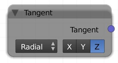
Tangents are all lines perpendicular to the normal of a face. So essentially all lines across a face, the most simple ones being the edges of the face. Since each face has an infinite number of tangents, Cycles has to decide which ones to use. By default these are following a hypothetical cylinder along the local Z axis of your object. If you use this node as an input for a texture, it will get projected onto your object as if it was on a cylinder that is being shrinkwrapped onto the object . This also means it will get stretched along the default directions of an .
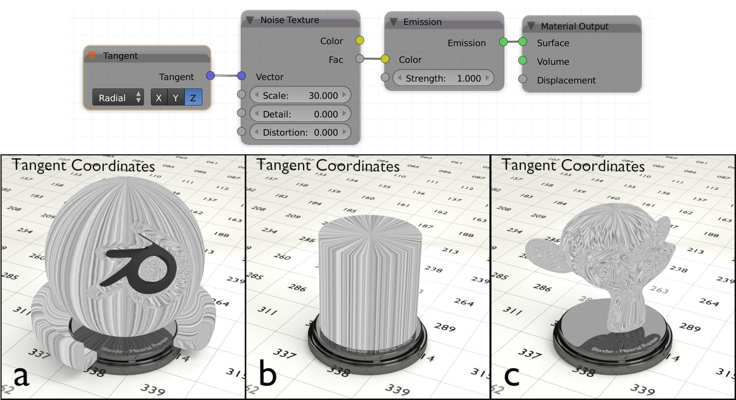
Fig. 4.7) The Noise Texture projected onto different objects along their tangents. In a) and b) you can see that the tangents follow a hypothetical cylinder along the object, while c) shows that they are a bit more unpredictable in complex meshes.
There are two types of projections.
Radial
Projects the texture onto your object as if it was coming from a cylinder around it. Only this projection type can be altered by the following X, Y and Z.
X
Rotates the hypothetical cylinder so it is oriented from left to right.
Y
Rotates the hypothetical cylinder so it is oriented from front to back.
Z
Rotates the hypothetical cylinder so it is oriented from up to down.
UV
Allows more control over the projections. If you switch to this type, you get the option of choosing a different UV map from your standard one (the one with the camera enabled in the data settings of the properties panel). If you leave it blank, Cycles will use the standard one. This way you can rotate individual islands on your UV map to change their tangents e.g. for the .
If you want to influence the tangent of certain areas, but not alter how your texture gets mapped onto your object, create a separate UV map and use the dropdown to select it.
RGB (R)
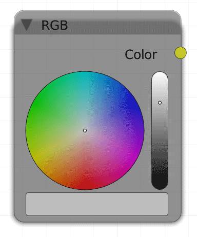
The RGB node lets you specify a color. This is useful when you want to use different shader nodes that need to have the same color input. Using one RGB input, you can change all colors at the same time.
Color
Outputs an RGB color.
Value (V)
The Value node outputs the number you specify. This is especially useful when you want the same factor to influence different nodes. By connecting their factor inputs to the same value node, you can change all those factors at the same time.
Value
Returns the value specified in the according field.
Geometry (G)
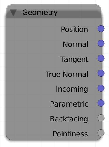
It returns information about shading points. These are basically the points on a surface hit by a ray. You can use the outputs of this node to change areas of your surface depending on their qualities. You can also use them as texture coordinates directly. All coordinates are in world space.
Volume shaders can only handle the position and the incoming vector.
Position
The position of the shading point in world space. So using this option will make a texture stay fixed in the scene, not matter how your object moves or rotates.
Normal
Uses the normals of the faces to get the input, will be taken into account with this option.
Blender will create three hypothetical axes, X, Y and Z. These are relative to your object's origin and rotation. The resulting vector from this output will then be calculated from the direction of the face's normal relative to the axes.
Only the angle will be considered, not the direction, so flipping the normals has no effect. Also the position of your objects or its individual faces are not taken into account, the output is calculated from the angle of the face’s normal direction, relative to the world X, Y and Z.
Tangent
Uses the tangents of the surface as an input. Identical to the with radial Z selected .
True Normal
This option will use the normals of the geometry only, ignoring bump- and normal maps. It also makes your object's surface look flat shaded, since the true normals ignore the from smooth shading.
Incoming
This input is dependent on the direction of the camera relative to the world space, as well as the position of the object in the frame. The orientation of the object is not taken into account, as well as the direction of individual faces. In short: It is the direction from the shading point towards the camera/point of view. You can use this to create your own reflection maps.
Parametric
This might not be mathematically correct, but let's put it this way: If you use this as an input for a , each face will get a gradient, starting from the vertex with the lowest index towards the opposite edge. You could also say, this method treats each face as if it was an UV island. If the polygons are irregular in proportions, the texture may become stretched. You can use this to project the same texture onto each polygon. Faces get triangulated before rendering.
Backfacing
Only outputs 1 for the back of a face or 0 for the front, nothing in between. Which side is considered front or back is determined by the surface normal. The direction into which the normal points is the front.
Hint : You can use this to add a holdout shader to the backside of an emission plane, so it only shines in one direction.
Pointiness
This option creates a black to white gradient across each face. The brightness is dependent on the steepness of the edges compared to the other adjacent faces. Crests or convex parts get colored white, plain areas will receive a medium gray and cavities or concave parts will be tinted black. The gradient has a great range, so it should best be combined with a color ramp node, to control the hardness of the gradient.
Internally, pointiness uses the same algorithms as the dirty vertex colors, which means that the resulting gradient depends on the mesh density. When working with low poly objects, baking ambient occlusion might be a better choice.
A common use-case for this node is to add wear or dirt to edges of an objects, as those parts are exposed the most in the real world.
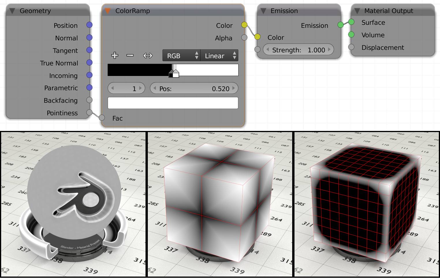
Fig. 4.8) Left: The test object with shader setup above. Convex parts of the object get brighter while concave ones darker. Note how close together the stops in the color ramp need to be. For this example the closeness has been exaggerated to show that values too extreme will make the topology of your object visible, as you can see in the rim of the logo and more subtle on the entire sphere.
Middle: A cube with one subdivision, using the pointiness attribute. Notice how the gradients stretch across the entire model and the edges get darker towards the middle. This is because there is too little geometry for the pointiness attribute to take effect.
Right: The same cube with higher subdivision level. Now the pointiness attribute is actually very useful.
Wireframe (I)
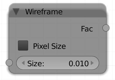
This input colors the edges of the faces of a mesh white while leaving the faces black without a transition. It has a size input that controls the thickness of the edges. You can choose the factor to be in BU, or pixels. The difference is: if you choose pixels, the edges have the same thickness independent of the camera distance. Since Cycles triangulates faces before rendering, you cannot use this to visualize quads. For that you should use the wireframe modifier, which is not part of Cycles but Blender in general.
Pixel size
Will make every edge the same size in pixels in your rendering, no matter how far away it is from the camera.
Size
The overall thickness of the wires.
Fac
This node will not output any color variations, but instead a map, where a wire would be white and everything else black.
Hint : Use this as a factor in a color mix node to use two colors.
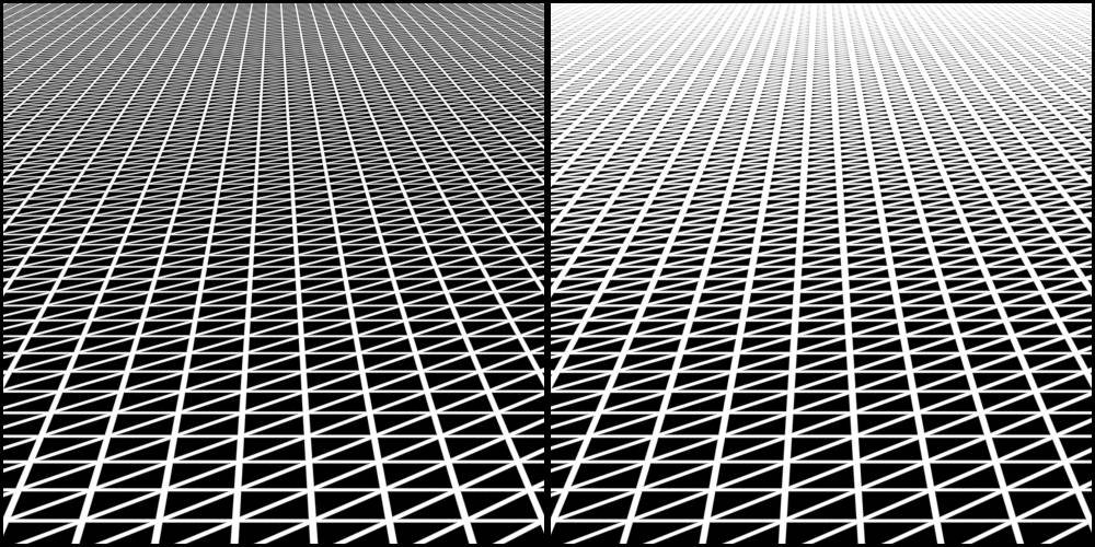
Fig. 4.9) A quad grid with emission shader. The strength is controlled by a wireframe node. Notice that the output is triangulated, the source is an all-quad mesh. Left: Size 0.02. Right: Pixel Size 6.0. On the left the lines are getting thinner towards the horizon while on the right the width is not changing with depth.
Object Info (O)
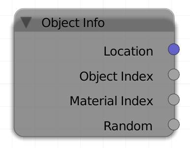
The object info node lets you influence shader features depending on several properties of your object. This is handy for letting objects with the same material look different from each other, depending on their following individual properties.
Location :
Use the world location of the object to generate different values. You get this value for every shading point on the object, contrary to Position of the . This can be demonstrated by using the location vector as input for a gradient texture. If you then move your object around, you will see its color changing.
Hint: Connect the vector output value to a color node and to single out the position for each individual axis. Negative values will result in black, but you can use the absolute operation of the math node if you want to move your object to a negative coordinate and still get a useful result from this node.
Object Index :
In the object tab in the properties panel you can specify an index for this object. The index is independent of the data block and material of the objects and is quasi used to group objects by their index. In this case all objects sharing the same index will receive the same output from this socket, so you can easily use different features on objects sharing the same material by assigning different indices to them.
Material Index:
Materials can also be indexed. However the index will be the same for every object with this material. You can use it to create a material that can be changed to a different one with one click on the material index field. The material index can also be animated and used with drivers.
Another use-case are node groups. Everything inside a node group works globally across material boundaries. By adding a Material Index input inside a node group you can make per-material changes to the node group without exposing inputs.
Random:
Returns a random number between 1 and 0. The number is generated at the time the material is assigned to the object. This means using different random input nodes will still result in the same value for each individual object.
Hint: Using this value as the input factor for a color ramp will sample the color at the position the number indicates.
Ha ir Info (H)
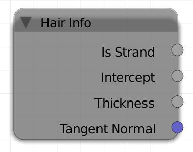
If you are using particle hairs, the Hair info node will help you distributing shader effects across the hairs.
Is Strand
Returns either 1 or 0 depending on the rendered part of your object being either a strand or not. You can use this output, if you want to put the hair material in the same slot as the object's. Use a mix shader with Is Strand as the factor.
Intercept
Returns a gradient along the hair. The root will be black and the tip white. This value is used best to feed a color ramp that can then fine control the colors along the hair.
Thickness
As long as the decrease of thickness along the hair is linear, intercept and thickness will produce the same results. But if the hair outline is more curved, or the tip is not 0 there is a difference. The brightness is depending on the thickness of the strand, thicker areas are darker.
Tangent Normal
The tangents are oriented along the hair, therefore the tangent normals are pointing away from it. It is useful for re-lighting of hair without changing the lighting of the rest of the scene.
Particle Info (P)
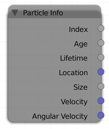
The particle info node allows you to use information about individual particles to influence their material. It allows for great control over a lot of attributes.
Index
All particles receive a unique index depending on the order in which they were born. Returns an integer (whole number).
Age
The time between the particle's birth and now in frames. Use it e.g. to fade out particles over time.
Lifetime
The entire span of life of a particle in frames. If you influence the lifetime of the particles with a random factor in the particle settings, particles can get a different attribute depending on how long they are going to exist. This value is fixed for each particle and does not change over time.
Location
You can get the world location of the particle. This way you could color them depending on where they are.
Size
Use this value to influence particles depending on their relative size. The size is not the absolute size, but rather the size the particle gets assigned by the size slider in the particle settings, its random value or a texture influencing the size over time.
Velocity
Gravity, damping effects, force fields and similar effects influence the particle's velocity, you can use this value to brighten faster particles.
Angular Velocity
P articles can rotate around different axis, for example the axis of the direction they are traveling in. This is what's called an angular velocity and you can color a particle based on its rotation speed.
Camera data (C)
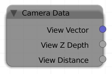
The camera data node can be used to give objects different types of materials depending on the angle of and distance to the camera. It is most commonly used to produce an antialiased mist pass that recognizes motion and depth of field blurs. It is created by rendering the same scene again, only this time all objects that are supposed to be influenced by the mist will get a material with two shaders, one bright one ( ) and a black one ( ) with either View Distance or View Z Depth as the factor of the .
View Vector
The view vector output is similar to the camera output of the node. The main difference is: It does not scale the texture depending on the distance to a surface.
View Z Depth
This outputs the distance of a shading point. However the distance is not the absolute distance from the camera, but to a hypothetical plane which is oriented towards the camera and contains a point on the face.
If this sounds too complicated, let me give you an example. If the camera is pointing along the global Z axis and looking at two objects that have the same Z position, but different X and Y their Z depth will be the same, as opposed to the view distance .
View Distance
Returns the absolute distance of a point from the camera.
UV Map (U)
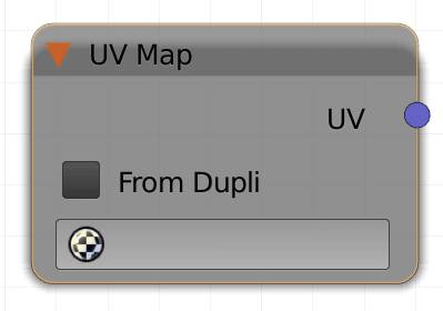
If you want to use a different UV map than the default one, you can specify it with this node. The standard map is indicated in the object data tab of the properties editor. It is the one with the camera symbol enabled . By default it is the first one you created.
From Dupli
Works exactly like the from dupli option of the node, fig. 4.1.
Selection field
Choose the desired UV map here.
UV
Outputs the UV coordinates of the designated UV map.

