Chapter 3: Output Nodes (O)
Every shader needs an output node to tell Cycles how to treat the object in render. There are three different outputs. The world output node can only be used with world materials, the other two work both for regular objects and lamps.
Material Output (M)
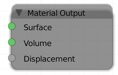
It is the most commonly used output, since it is needed to make objects visible.
Objects will be pitch black unless there is a material output node in the material setup. The uppermost input is the most commonly used, as it determines the surface of your object. The volume socket is necessary for volumetric effects like fire and smoke. It only works with the three volume-enabled shaders: , and . The displacement input is gray, indicating that it uses grayscale information. Black parts will make the surface appear to have dents, while brighter parts will fake parts standing out. This effect is inferior to the normal mapping, but it will still greatly increase realism of your objects, since hardly any surface found in nature is spotless.
There is a feature marked as experimental to use actual displacement. This means that instead of bump mapping the actual geometry of your object is being altered in render. This is similar to the displace modifier, but offers a few more options. In order to get access to these options you need to switch the feature set to “Experimental” ( ). There are 2 advantages of this new feature:
- You can use Cycles’ procedural textures with this method, while the displacement modifier takes image or BI procedurals only.
- You can also use it on objects like metaballs or curves that cannot handle a displacement modifier at all.
The true displacement option must be turned on for every object individually. It can be found in the object data tab of the properties editor.
Method
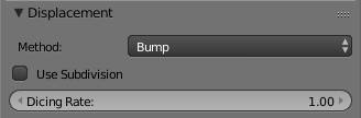
The displacement settings are experimental at the moment (v. 2.77), so you need to set your feature set to experimental in the . They don’t appear to be updating properly, so if nothing changes, try checking and unchecking the use subdivisions box. But there still may be a considerable difference between preview and render, so you might want to test both.
Bump
Will use the input of the displacement of the output node as a bump map.
True
Will use the input of the displacement of the output node to actually displace the surface similar to a displace modifier. You need a lot of faces to get a useful result out of this, so there is a hybrid option.
Both
Will combine the fake and real displacement. This is a nice compromise if you want to see real displacement, but still do not want to heavily subdivide your object.
The following two options only apply if the upper one is set to either true or both.
Use Subdivisions
This option will automatically subdivide your mesh during rendering.
Dicing
If use subdivisions is turned on, you can dice your object. Setting the value lower than 1 will subdivide your object, similar to a subsurf modifier. If it is an option, better use the latter, because dicing actually seems to be cutting your object, see fig. 3.1 e).
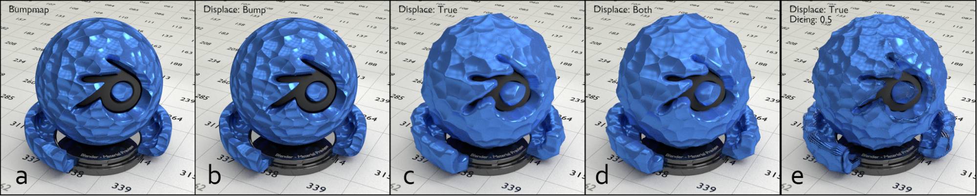
Fig. 3.1) Different methods of adding detail to a surface. All use the same voronoi texture for the displacement, but the methods are different.
a) Texture plugged into a bump node.
b) - e) voronoi connected to the displace socket of the material output node.
b) default method: bump
c) experimental: true
d) experimental: both
e) experimental: true, subdivided by the dicing option with a rate of 0.5.
In fig. 3.1 you can see the difference between different methods of displacement. There is not much difference between a and b, but with the you can displace each shader individually. The key difference between bump maps and true displacement is especially noticeable if you compare the rim of the object in b) and c). Note how in b), even though the surface looks very bumpy, the outline of the object is still spherical. Whereas in d-f the rim also gets displaced. This is much more realistic, but it requires your mesh to be heavily subdivided. A good compromise can be seen in d) where both true displacement and bump are in use. c) has more rounded corners, which is not always desirable, so you can combine the effect of displacing your mesh, to get the required topology, and still use the bump effect to produce hard edges. e) demonstrates why subdividing your mesh manually is usually preferable to the use subdivision method - at least at the moment. The surface receives more detail, but the object is also split into stripes.
Back to the node’s inputs:
Surface
Expects a surface shader output.
Volume
Expects a , or output.
Displacement
Use this to apply a bump or displacement map to your entire material.
Lamp O utput (L)
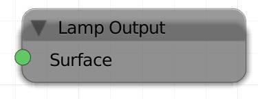
The lamp output is traditionally used for lamps only. Its input is still called surface, even though a lamp object (sun, point, spot or area) does not have an actual surface.
Surface
Expects an output.
World Output (W)
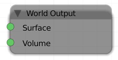
To influence your environment, your material needs a world output, which works best with a background shader connected to it. It works similar to an emission shader but rather than light being emitted by one object only, it will act like a huge sphere all around your scene, shining light onto it, in the way you specified.
Surface
Expects a output.
Volume
Expects a , or output.

