Chapter 14: Render Settings
There are a number of settings that can drastically influence the render speed and quality of your scene. Those settings can be found in the render tab of the properties editor. This chapter will skip parts that are not Cycles specific like output image formats.
Render
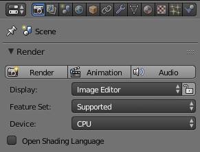
The top two rows in this panel are the same for Cycles as for other render engines. Hitting the Render button (F12) will start the rendering process for the current frame. Animation (CTRL + F12) will render all frames in the current frame range. Audio will just create a mixdown of all audio sources in the current scene for the current frame range.
Display allows you to select the space where the render result will be shown: Image Editor will use any open image editor windows. If none is there, the 3D view will be changed to an image editor. Full Screen will change the interface to full screen mode with just an image editor where the result is shown and New Window will create another window detached from the current one. Keep UI can be very useful. It will also use an open image editor, but if none is there, rendering will start in the background without showing the result, which will be a little faster and save some Ram.
The little lock next to the selection box will make the entire UI of Blender passive. You will not be able to click anywhere anymore. The only way to stop the render process will be hitting the ESC key on the keyboard. But it saves some VRam so if you are rendering on the GPU and get an “Out of memory”-error, selecting this checkbox might help.
Feature Set
Keeping this at the default of Supported will give you all features of Cycles that have been thoroughly tested. Experimental will allow you to use additional features that are prone to changes, might be unstable or have otherwise unwanted side-effects. By the time of 2.75 this will give you access to True Displacements (see - subsection Method ) .
Device
This setting will only show up when you have set a compute device in the user preferences . CPU will render the scene on your computer’s main processor. It is the default and supports all features of Cycles. GPU will render the scene using your graphics card (or on multiple of them at once if you have several). Due to the complexity of parallel programming on GPUs and limitations of the architecture some features of Cycles are not available when rendering on GPUs. is one example without a GPU port that will stay on CPU-only for quite a while. Even the manufacturer of a graphics card (nVidia or AMD) can make a difference in the supported features. For a full and updated list check out the .
Another limitation of GPUs is the amount of textures a scene can use. For nVidia GTX 4xx/5xx cards the limit is 95 textures, for cards of the series GTX 6xx and above it’s 145 textures.
Open Shading Language
When the Device is the set to CPU , the checkbox for Open Shading Language (OSL) appears. This will allow you to use OSL shaders with the node.
Sampling
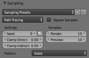
The more samples you choose the more often camera rays are cast onto the scene, clearing up the image. The render samples apply once you press render or F12 to obtain the final image.
The preview samples refer to the preview render in the viewport. You can set the latter to 0, causing Blender to keep sampling the image until it gets interrupted.
Under the presets you can already choose between preview and final . Both presets turn on square samples and set the number of render and preview samples to either 12 and 6 or 24 and 12 respectively. The latter setting should be enough for most non-interior scenes. You can also store your own presets. To do so, choose any number of samples press the + button and enter a name to store it, so you can later on restore those settings by a single click.
Sampling Presets
Either choose or store a render preset. It only refers to the number of samples for render and preview and whether to square them.
Path Tracing
You can choose between regular and branched path tracing ( ).
Seed
Seed for the random factor of the sample distribution. In order to be able to render the same image on several machines with exactly the same output, this input is only pseudo-random. If you render an animation, you will actually see a pattern of noise staying in one place as the animation continues. Animating it will make the noise flicker in an animation instead of staying in one place. Since this is actually close to film grain, it is usually best to animate this value so it is different in each frame. Since Blender 2.75, there is a small icon next to the seed property that can be used to create an animated seed automatically.
Clamp Direct
Does not allow any sample from direct light to be brighter than the value you specif y.
Clamp Indirect
Does not allow any sample from caustics or global illumination to be brighter than the value you specify.
For more information on clamping and how it helps to reduce fireflies refer to in the chapter .
Square Samples
Automatically uses the square of the values specified in the render and preview field. So 10 becomes 100, 4 becomes 16 etc. This is considered more artist-friendly by some users because to get rid of half the of noise in a scene you have to multiply the amount of samples by four. When setting square samples , to get half the noise you just need to double the samples. But keep in mind that this will still quadruple your render times so use this feature with caution. Square samples is the default behavior of other path tracing engines like Arnold.
Render
The number of samples to calculate in render.
Preview
The number of samples to calculate in the rendered viewport preview. You can set this to 0 for infinite samples.
Pattern
The way the camera shoots rays is not completely random, thus patterns can become visible in the noise. Cycles is offering two different patterns, Sobol and Correlated Multi-Jitter . If you notice clumps of noise when rendering, try using the other pattern.
In general, Correlated Multi-Jitter takes a little longer but results in less noise when only very few samples are used (i.e. < 50).
Branched Path Tracing
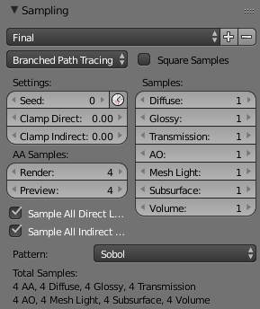
Branched path tracing can be very effective when it comes to reducing render times. The rays are divided into diffuse, glossy, transmission, AO, mesh light, SSS and volume. The value for these settings will be multiplied by the AA samples , so when the AA base rays are 4 and the diffuse rays are set to 100, each diffuse surface will receive 400 (4 * 100) samples to calculate, while transparent background will be be rendered with just 4. So you can prevent a lot of rays from being cast, which saves render time. Another reason why branched path tracing is often faster is that the secondary rays are cheaper to compute than primary / AA ones.
The live preview will take longer to update with Branched Path Tracing because it will only update once for each AA Sample . For example, if you have a scene consisting completely of diffuse surfaces and set AA samples to 4 and Diffuse Samples to 100, the viewport will only update 4 times, once for each 100 diffuse samples fired.
AA Samples
The number of rays fired from the camera. They are called AA samples because their primary purpose is anti-aliasing, but they also define how noisy areas with motion blur and depth of field will become. Turn these up to get rid of jagged edges and noise in blurred areas. A rule of thumb is to use at least 16 for perfect anti aliasing and much more for depth of field and motion blur.
The reason why you also need AA samples for defocused and motion blurred areas is the following: Consider a scene where a diffuse object is in front of a black background. AA samples are set to 4 and diffuse samples to 100. The object itself will get rendered with 400 samples, but the background only receives 4. Defocused areas as well as motion blur will produce pixels where 4 rays hit the background and thus no more sampling occurs while for a pixel next to it in the blurred area a ray might hit the diffuse surface, making Cycles fire 100 rays from that spot. The result is a lot of noise blurred areas.

Fig. 14.1) A plane with white emission shader rendered at a resolution of 16 x 16 pixels with Branched Path Tracing. From left to right: 4 AA Samples, 8 AA Samples, 16 AA samples. The diagonal lines get less and less jagged the more AA samples are used.
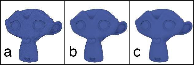
Fig. 14.2) Renderings using branched path tracing.
a) 1 AA, 1600 diffuse samples.
b) 4 AA, 400 diffuse samples.
c) 16 AA, 100 diffuse samples.
The Monkey has a purely diffuse material, in all 3 renderings it is sampled by the same amount of rays (1600). Yet too few AA samples result in aliasing artifacts at the edges and an overall more noisy look.
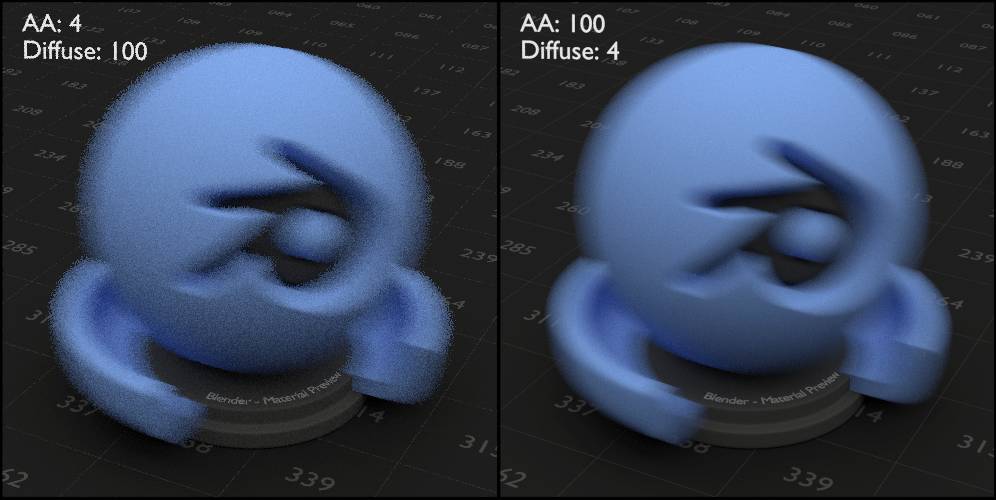
Fig. 14.3) A fast moving object with diffuse surface and motion blur enabled. A low amount of AA samples result in heavy noise in the blurred areas. A suitable amount of AA samples gets rid of the noise and allows to reduce the diffuse samples.
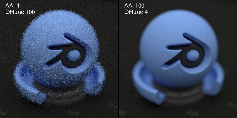
Fig. 14.4) Increasing AA samples gets rid of noise in areas blurred by the depth of field (DoF).
Samples
The amount of additional samples per AA sample used for each shader type. They get cast once an AA sample hits a surface for each shader node in the material. So if you set Diffuse to 10 and Glossy to 2 and your material has a diffuse shader mixed with a glossy shader, 10 diffuse rays and 2 glossy rays will be cast from the spot where an AA sample hits a surface with said material (see fig. 14.5).
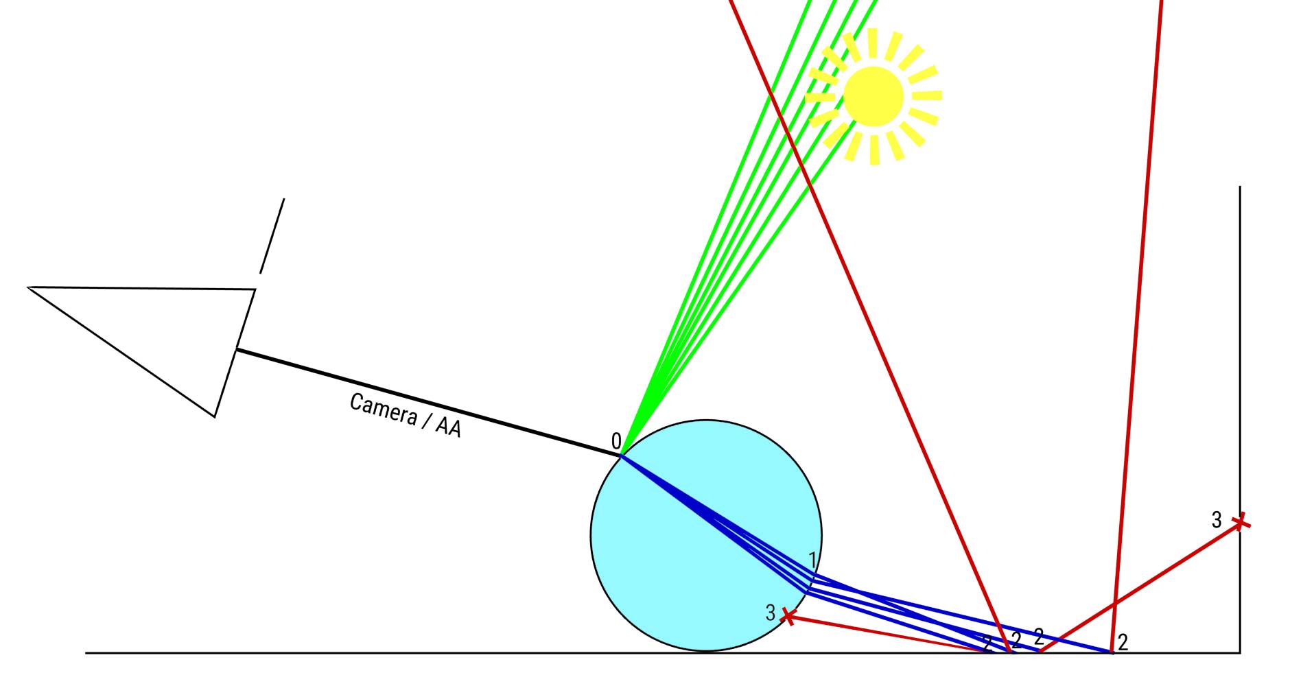
Fig. 14.5) Example for branched path tracing (BPT) with 6 glossy samples, 4 transmission samples and 8 diffuse samples. An AA ray hits a glass shader (bounce #0), which is a combination of glossy and refraction shader. From that point, 6 glossy rays are cast and 4 transmission rays. The transmission rays continue their paths, but since they are no longer AA rays, no additional rays are cast when they bounce further (#1). Even when they hit a diffuse surface, no further diffuse rays are cast (bounce #2). After the AA bounce, the rays act like they would in regular path tracing.
Note: For the sake of simplicity, the casting of shadow rays was omitted as well as the probability at bounce #1 that rays get reflected instead of transmitted.
Sample All Direct Lights
When a ray hits a surface, a shadow ray is sent towards a random lamp in the scene to measure its light contribution at that point and whether the point is in a shadow area. By checking this setting, shadow rays are sent to all lamps in the scene at the first bounce. This will greatly reduce noise in scenes with more than one lamp, but it will also take slightly longer to render (see fig. 14.6).
Sample All Indirect Lights
Same as sample all direct lights but for rays that have bounced at least once, thus contributing indirect light (see fig. 14.7). It can be combined with sample all direct lights. Since there are usually more indirect bounces than direct ones, this method will slow down rendering more than the sampling of all direct lights, but it will clear noise from indirect light very well.
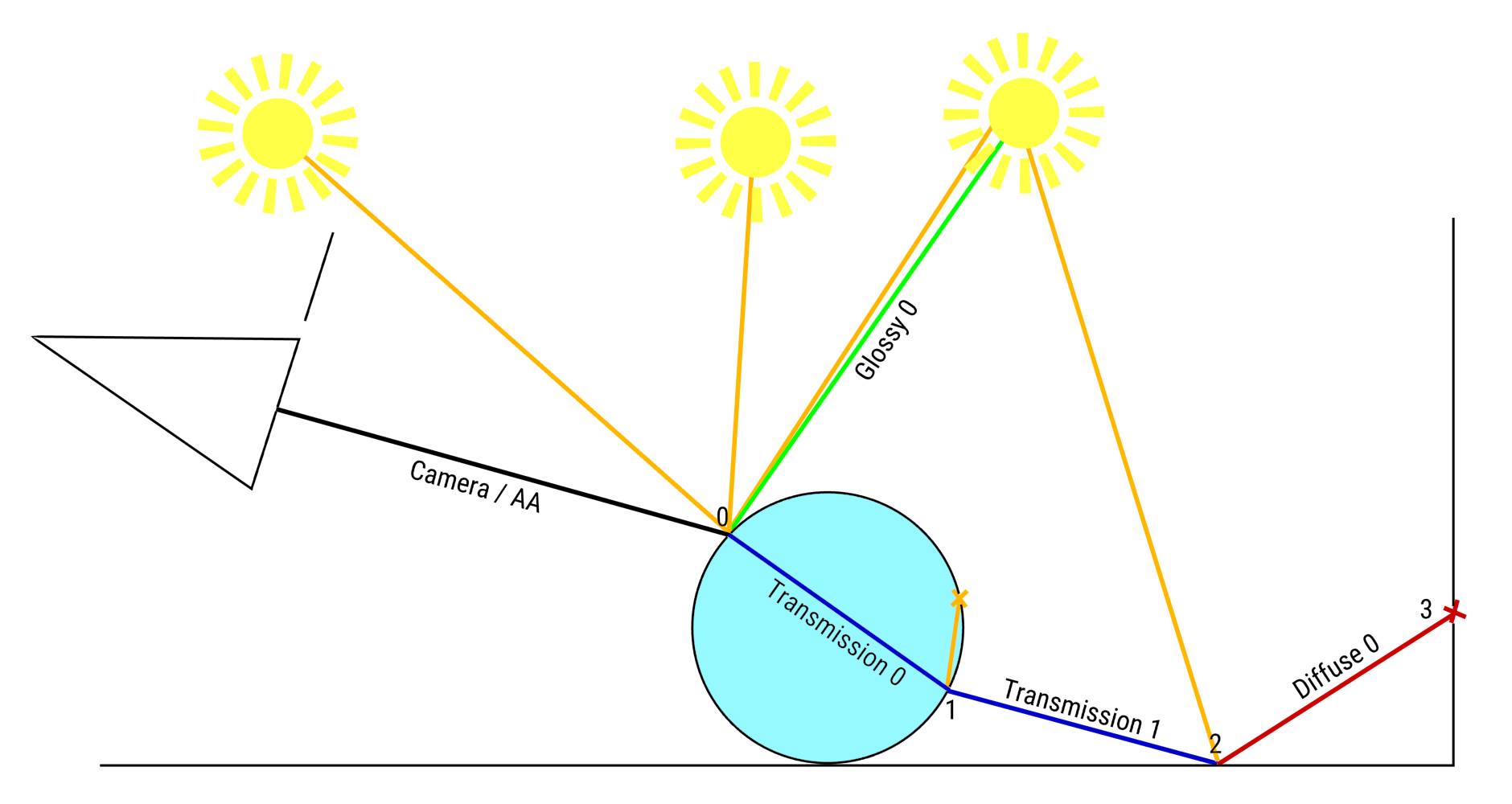
Fig. 14.6) Branched path tracing with sample all direct. For the first bounce (#0), shadow rays are cast towards all light sources in the scene. For subsequent bounces, one random light source is chosen (#1, #2).
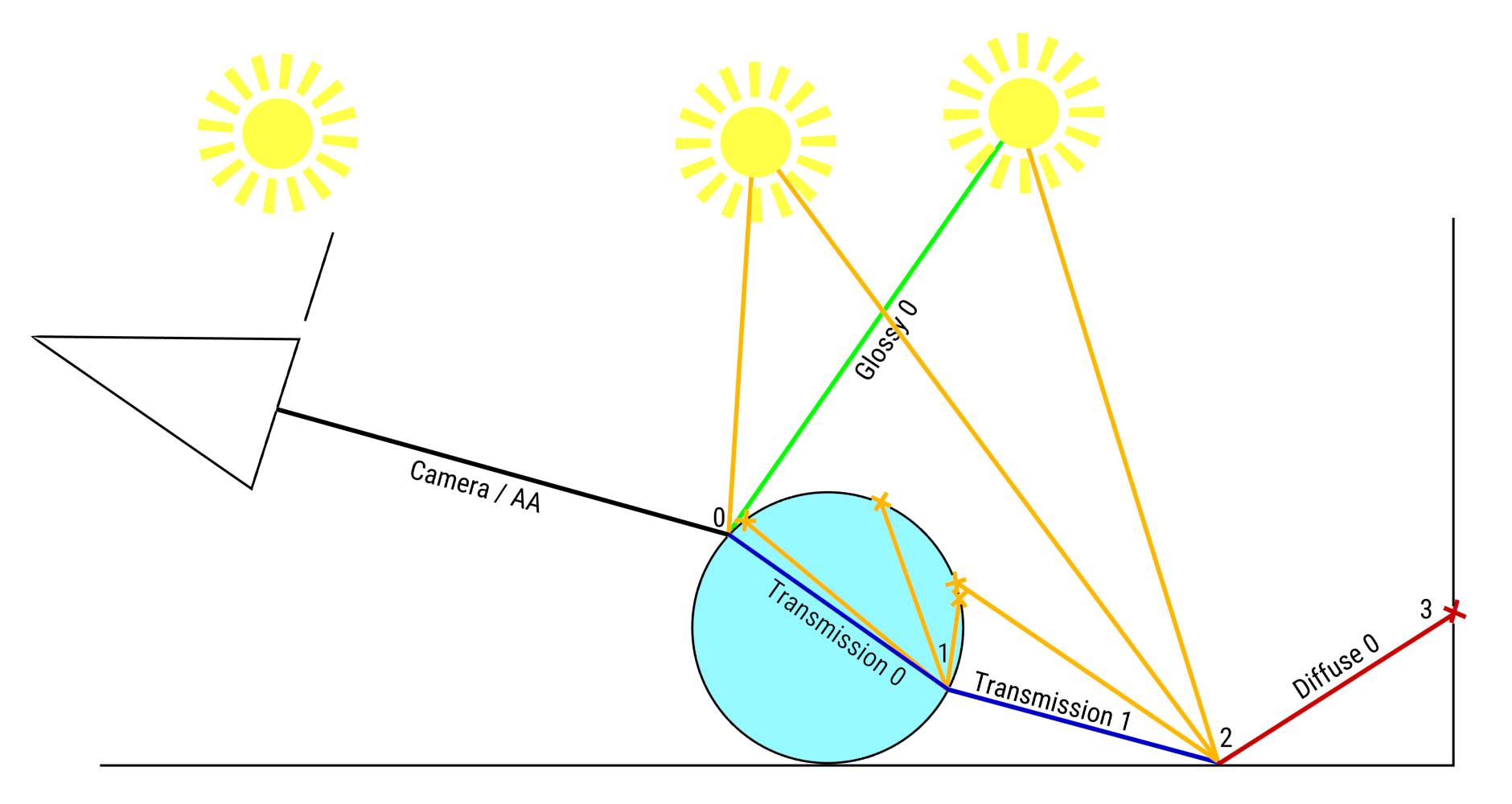
Fig. 14.7) Branched path tracing with sample all indirect. For all secondary bounces (#1, #2), shadow rays are cast towards all light sources in the scene. For the first bounce, one random light source is chosen (#0).
Volume Sampling
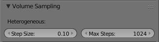
The settings here apply only to . They are not sampled at every possible point because that would take an infinite amount of time. The ray rather get sampled along the path the ray takes through the volume in segments or steps of a given length.
Step Size
Length of the sampling step. Lower values produce more accurate results but also increase render time .
Max Steps
How long a ray may travel through the volume before giving up. Higher values produce more accurate results but also increase render times.
Light Paths
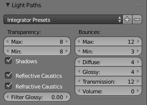
Under light paths you can set the amount of bounces per ray type and turn on or off features like caustics and colored shadows of transparent objects. Some bounces settings have a max and min . When min is set to a smaller value than max , the path will be terminated at random once more than min bounces are reached.
Generally you won’t really notice a difference between 9 and 10 diffuse bounces , but If you set them to 0 you will no longer get indirect light in your rendering and therefore no global illumination effect. The number of glossy bounces determines how many times a glossy surface will reflect itself in other glossy surfaces.
If you put several glass or translucent objects behind each other, you might have to increase the number of transmission bounces . If you put more transmission surfaces in a row than you allow bounces, coming from the camera, the furthest ones will be black.
The same goes for transparency bounces, although these will only affect transparent materials. If you want to render a complex object semi transparent, you might find a lot of black “artifacts” in your scene. increase the amount of transparency bounces to counter this effect.
The max setting for bounces will influence all other settings except for the Transparency Bounces . For example setting max to 0 will result in direct light only, no matter what type of shader, with the exception of transparent surfaces.
Integrator Presets
The presets allow you to quickly access common setups. As of version 2.77 of Blender, it ships three different presets:
Direct Light: This preset will give you a result similar to Blender Internal. Renders very fast with little to no noise.
Full Global Illumination: All Bounces are set to 128 except for the minimum amount. Should result in perfect lighting, but also slow rendering speed. If there is too much noise, try increasing the Min Bounces .
Limited Global Illumination: A compromise between the two extreme setups. Has caustics turned off but will give you indirect light from diffuse surfaces.
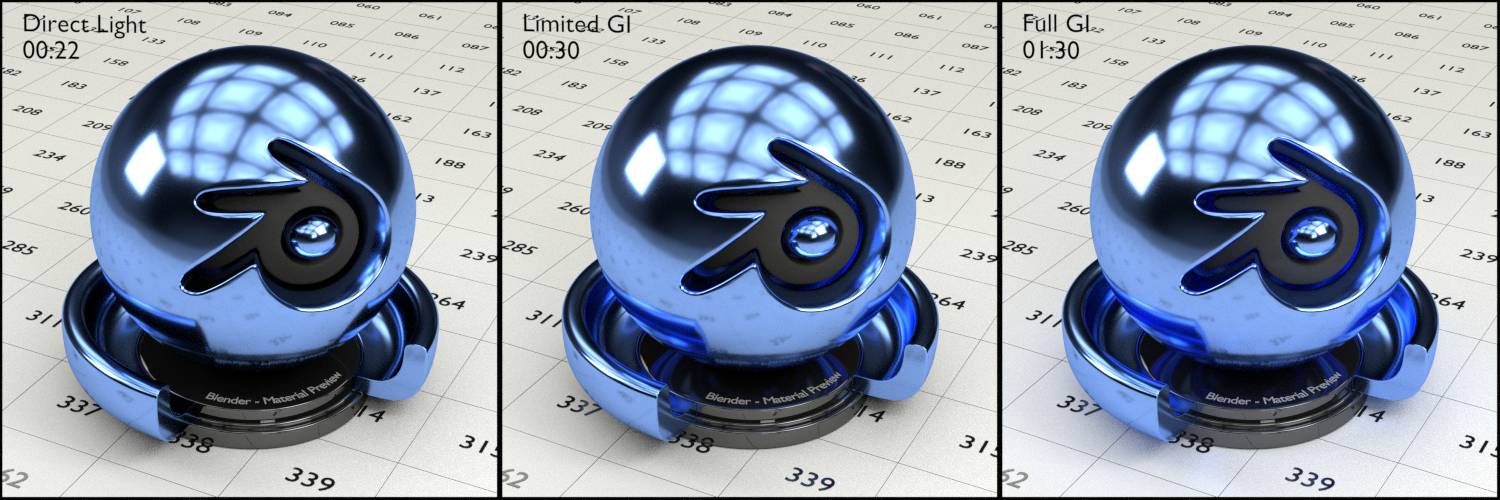
Fig. 14.8) Test scene with glossy shader.
Left: Direct Light. Render time: 00:22
Middle: Limited Global Illumination. Render time: 00:30
Right: Full Global Illumination. Render time: 01:30
While full global illumination has the most detailed render, including multiple inter-reflections, the render time in this simple scene is three times longer than with limited GI.
Transparency
This setting is independent from the Min and Max for regular bounces. Only affects the .
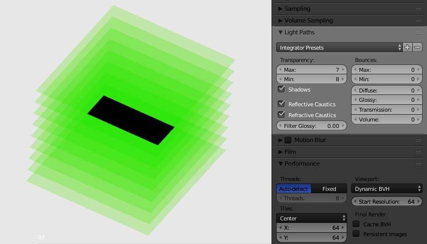
Fig. 14.9) Transparency settings. On the left is an array of 8 planes with a green transparent shader. The transparency max is set to 7, so where all 8 planes overlap a black area appears. Note that the min is higher than the max, but this is being ignored by Cycles.
Max
Every time a light ray touches a surface it is considered a bounce, no matter if it passes straight through, gets bent or actually bounces off it. In this example (Fig. 14.9) the maximum interactions between a specific light ray and transparent surfaces is set to 7, while the object consists of 8 planes. Therefore the light gets terminated after the 7th passing through a surface and the shading points where this occurs become black.
Min
Setting the minimum amount of bounces to a value lower that the max will allow Cycles to use probabilistic termination of individual paths. This means after reaching the minimum bounces, the ray has a chance to get terminated. While this saves render time, you will also see more noise in the scene, because terminated paths are not accurate. If you encounter noise in certain areas, try setting Min = Max.
Shadows
This allows to pass through transparent shaders, also recording any tint they might get from them. Since this only applies to shadow rays, you will still get tinted transparent shadows when this option is turned off, it will just take much longer for them to clear up. Note that rays travelling through the glass shader are considered transmission and thus not affected by this setting.
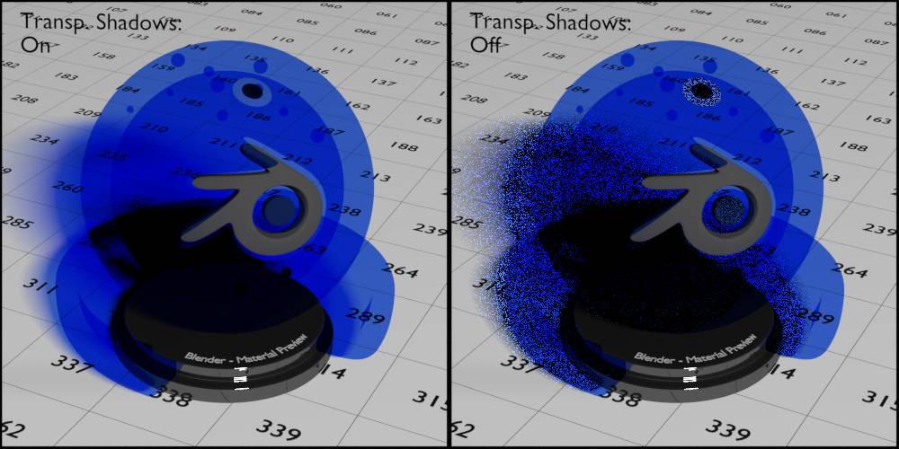
Fig. 14.10) Test scene with all lights turned off except for one. The test object has a transparent shader. Rendered with 500 samples.
Left: Shadows turned on.
Right: Shadows turned off. The shadow still gets tinted, but it will take a very long time to clear up. Even after 500 samples there still is a lot of noise.
Reflective Caustics
One of the effects of reflective caustics becomes evident, when you accidentally (I hope) blind someone with a watch reflecting the sunlight. Reflective caustics are caused by light bouncing from a diffuse surface onto a glossy one and then into a light source.
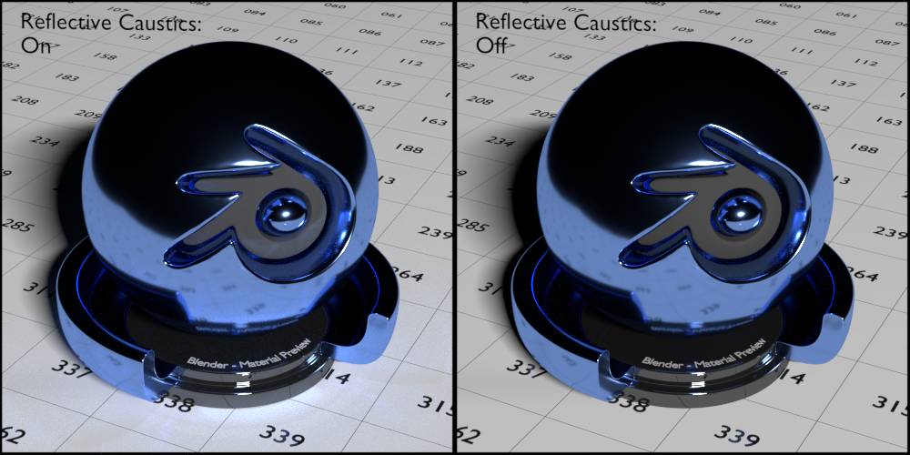
Fig. 14.11) Test scene with all lights turned off except for one. The test object has a glossy shader with roughness 0.02. Rendered with 10.000 samples.
Left: Reflective Caustics on.
Right: Reflective Caustics off.
Note that reflective caustics are often subtle, but they still add realism to your scene, as they are very similar to bounce lights from diffuse surfaces.
Refractive Caustics
Refractive Caustics are similar to transparent shadows but for transmission shaders like Glass or Refraction. Using a magnifying glass in bright sunlight, you can incinerate things. This effect is due to refractive caustics. Rather than absorbing light the magnifier converges light, so bright areas appear behind glass objects when they are hit by sharp light.
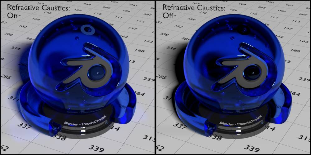
Fig. 14.12) Test scene with all lights turned off except for one. The test object has a glossy shader with roughness 0.02.
Left: Refractive Caustics on. Rendered with 50.000 samples.
Right: Refractive Caustics off. Rendered with 20.000 samples.
Note that with refractive caustics off, the small ring inside the object is completely black, same with the dot in the Blender logo.
Both types of caustics are a major cause of fireflies, so turning them off can help you get rid of them by sacrificing some realism. Refractive caustics are more prone to fireflies than refractive ones, though.
Filter Glossy
Glossy shaders that have a Roughness > 0.0 will benefit from this setting. When a diffuse ray hits a glossy shader, Cycles will treat that shader as if the roughness was way higher. This results in less noise and fireflies but also in less realism.
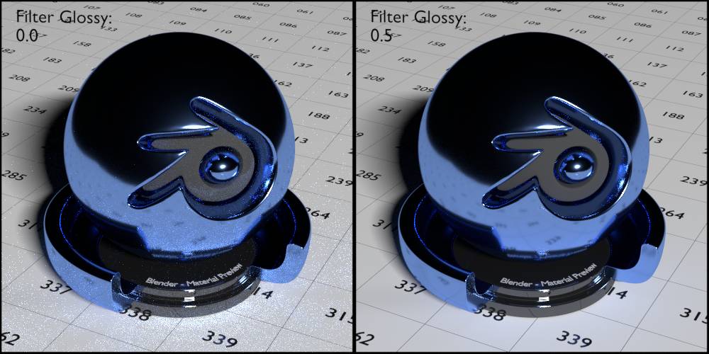
Fig. 14.13) Test scene with all lights turned off except for one. The test object has a glossy shader with roughness 0.02. Rendered with 500 samples.
Left: Filter Glossy 0.0. The caustics on the floor are pronounced, but very noisy.
Right: Filter Glossy 0.5. The caustics on the floor are blurred and only slightly visible, but almost no noise.
Note that the noisy parts in the test object where glossy rays hit a glossy surface are exactly the same in both images because bounces from glossy to glossy are not affected by filter glossy.
Motion Blur
Motion blur is the effect of fast moving objects getting blurred. It comes with a slight penalty on render performance and blurred areas are more noisy in general, that’s why it is turned off by default. Cycles supports motion blur for the camera (including zooming), object motion (translation and rotation only, no scaling) and deformation motion blur, which has to turned on separately for each object. Cycles calculates the MB by comparing the location of an object at a frame is compared to the location at the frames before and after. At the moment there is no calculation of what the object does exactly between those frames, so the blur will always follow the straight connection between the position of the object in the frame before, the current and the next frame. But since a frame is only an infinitely short moment of a - theoretically - fluent motion, this may look odd. In reality an object can make all sorts of crazy movements in 1/50 seconds, so a blur would in most cases not appear straight.
For more information on the phenomenon consult the .
Position
When the virtual shutter is fully opened. You can chose between:
Start on frame - The shutter opens at the current frame, the trail thus is behind it.
Center on frame (default) - The shutter is open at the current frame, the trail this exactly in the middle.
End on frame - The shutter closes at the current frame, the trail this is before it.
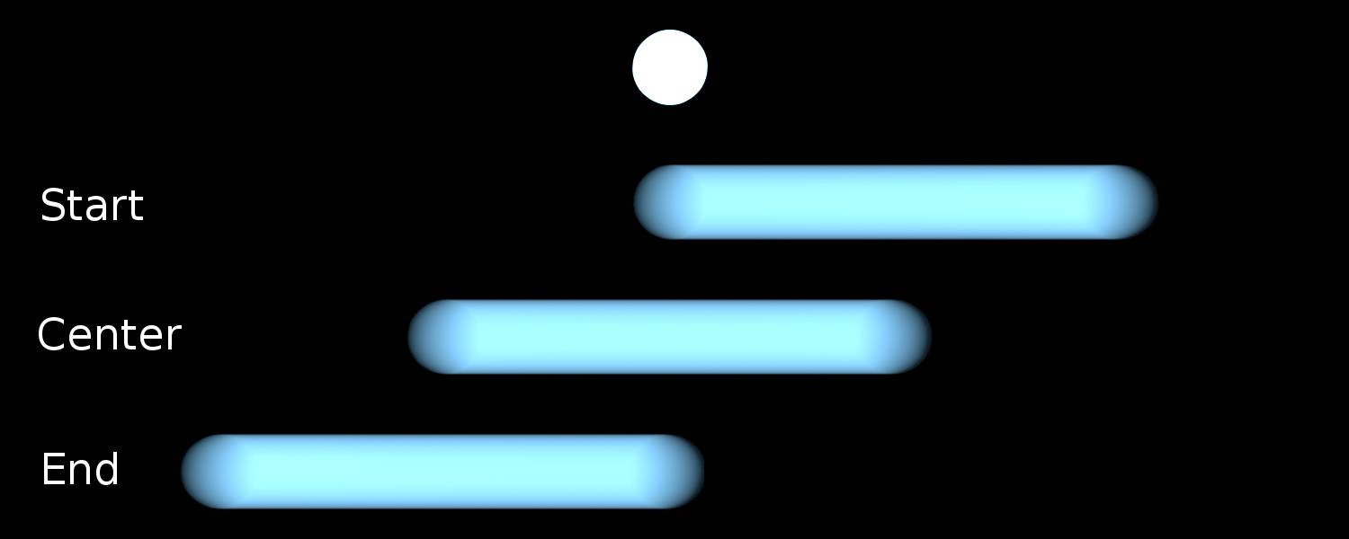
Fig. 14.14) Shutter position. A fast moving sphere with emission shader is rendered with the following settings:
Top: Motion blur off.
2nd: Start on frame.
3rd: Center on frame.
4th: End on frame.
Shutter
The shutter speed in frames. Higher values result in longer blurs.
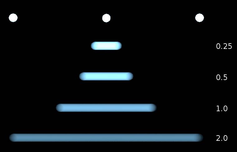
Fig. 14.15) Example of shutter speeds. At the top the position of a sphere with emission material on three consecutive frames. Below the resulting blur with different shutter speeds: 0.25, 0.5, 1.0 and 2.0.
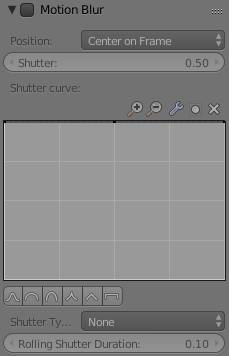
Shutter Curve
A real world mechanical shutter does not open and close instantaneously. This of course affects the look of motion blur. The shutter curves allow to simulate the opening and closing, but also some artistical effects.
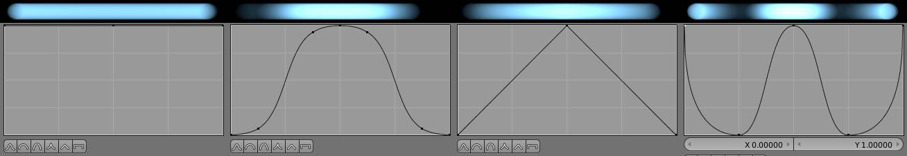
Fig. 14.16) Examples of custom shutter curves and their effect on the look of motion blur trails.
Shutter Type
Digital Cameras using CMOS sensors suffer from an effect called rolling shutter. The sensor scans the rows one-after-another and not all at once, straight lines get bent when panning with the camera. By default, Cycles ignores this. But when you set the Shutter Type to Top-Bottom , you will get the same bending and wobbling that occurs with real digital cameras. This feature is perfect when you want to integrate CG elements into a video with rolling shutter.
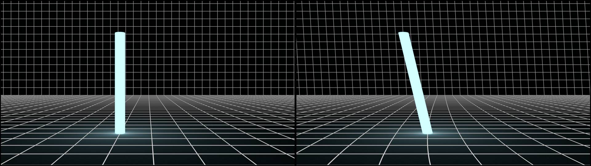
Fig. 14.17) Camera passing by a pillar with emission shader.
Left: Shutter Type: None, motion blur off.
Right: Shutter Type: Top-Bottom (rolling shutter duration set to 0.0 to avoid motion blur).
Rolling Shutter Duration
You can combine the rolling shutter effect with motion blur by increasing the duration. A value of 0.0 result in just rolling shutter and no motion blur, 1.0 results in only motion blur and no rolling shutter. Values in-between result in a combination of the two effects.
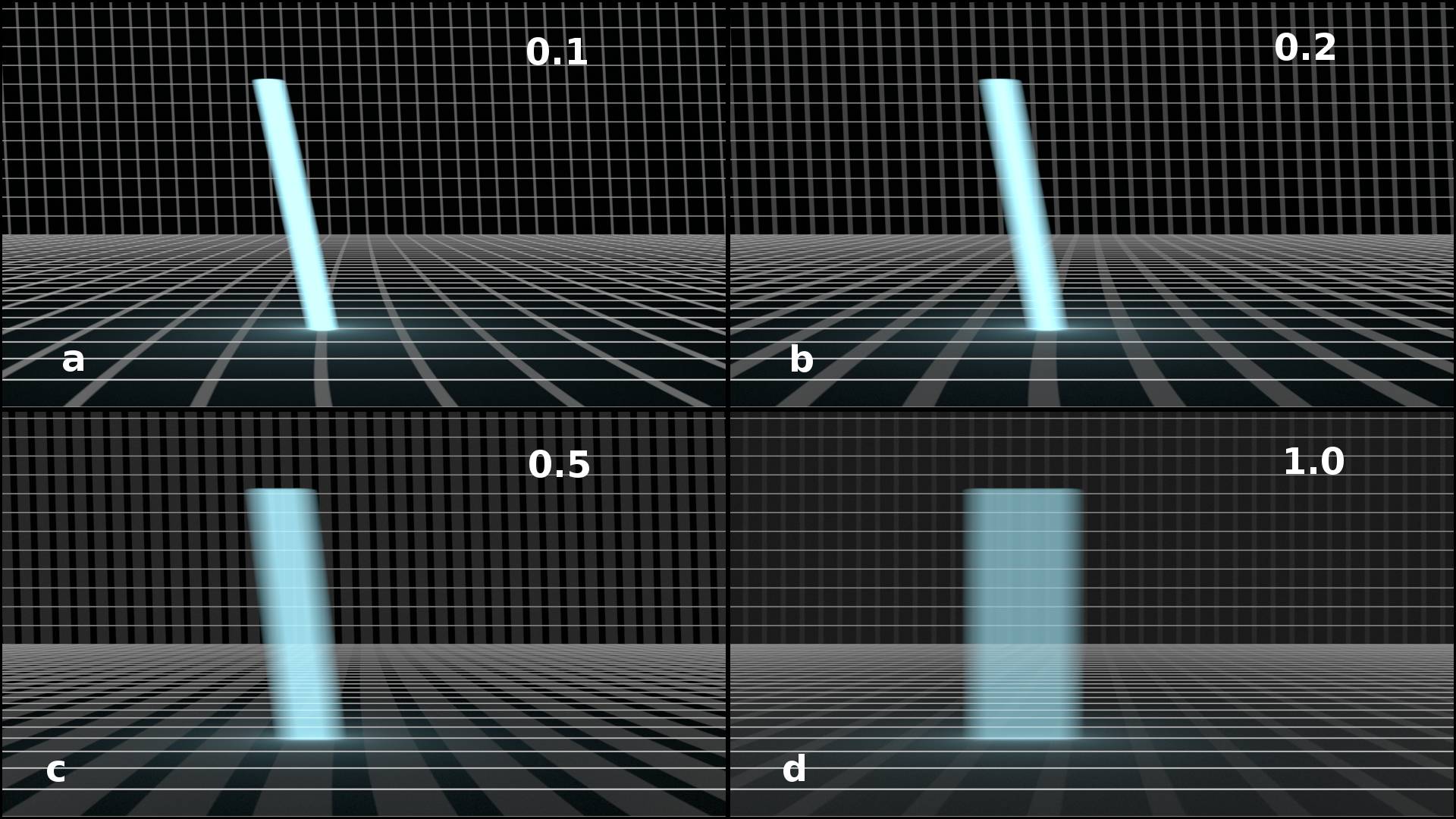
Fig. 14.18) Camera passing by a pillar with emission shader.
a) Rolling Shutter Duration : 0.1
b) Rolling Shutter Duration : 0.2
c) Rolling Shutter Duration : 0.5
d) Rolling Shutter Duration : 1.0
Rolling shutter and motion blur is a trade-off. The more motion blur, the less rolling shutter.
Film
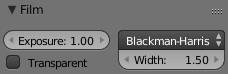
Here you find settings that affect the entire canvas or image. In analogy to a film strip used in analogue cameras, this panel is called film in Cycles.
Exposure
This property allows you to change the brightness of the entire scene right in the viewport (and of course also in the final render) without the need for post-processing / compositing.
Transparent
Turning this on will make those parts of your image that show the background or a transparent instead. Those parts are usually referred to as the alpha channel of an image and is - among others - not supported by JPGs and the transparent parts will be saved as black.
Pixel Filter Type
On the right you can find a drop-down menu which allows you to specify which method is used for filtering the samples that make up the pixels of the image. It contains three options: Box , which is a really simple filtering type that results in more noise and less anti-aliased edges, Gaussian and Blackman-Harris (the default).
For the latter two, you can specify a filter width in Pixels. The default of 1.5 is perfect for most cases. If you want a slightly sharper render, try reducing it. If you have a scene with very small geometry that has a repeating pattern that let’s you encounter aliasing, try increasing the filter width until the aliasing is gone. This will also slightly blur your render so use it in combination with .
Blackman-Harris can yield subtle but noticeable improvements over Gaussian in extreme cases like wireframes or high- textures.
Performance
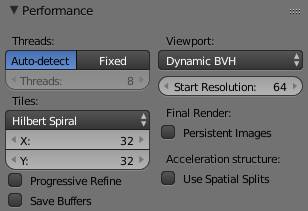
The settings you can find here will affect render time and the workload of your machine.
Threads
When rendering on the CPU, the amount of threads defines how many cores are used. Auto-detect will always use the maximum, which results in the fastest render speed but can reduce the responsiveness of your system as a side-effect. To cope with this, you can set the threads to a fixed number. If your CPU has 4 cores, setting the threads to 3 will keep one core free for other usages and thus you can render in the background and still use your machine.
Another reason to turn on fixed is when you want to render an animation on both CPU and GPU. Each GPU you have installed will max out one core of your CPU when rendering. To avoid performance losses, you should set the threads to #cores - #GPUs in that case.
Tiles
When rendering, Cycles is breaking down the job into parts. Those parts are called tiles in Cycles. In other render engines they are sometimes called buckets.
In the drop-down menu you can specify which parts of the image are rendered first. This does not have any effect on the overall rendering speed but rather allows you to see some areas of your image before others. The default setting hilbert spiral will start at the center of the image and move onwards counter-clockwise in a spiraling fashion, allowing you see the parts on the right next, then the parts on the top, then on the left and so on.
Center will start the render process in the middle of the image and move on in a circular fashion. The other settings will render line-by-line, you can choose between right to left, left to right, top to bottom and bottom to top .
On CPU, both hilbert spiral and the line-by-line options will render slightly faster than center because shuffling of data in memory can be reduced if tiles are close together.
X and y allow you set the size of the tiles in pixels. As a rule of thumb set it to 32 x 32 for CPU and 256 x 256 for GPU rendering. For optimal settings, refer to and in the chapter .
Progressive Refine
Instead of rendering each tile until it is done, the entire image is rendered sample-by-sample. This way you can keep your image rendering until the noise has cleaned up. Internally, the rendering still happens in tiles. This way a lot of data has to be shuffled around for each sample, re sulting in render times up to 60% slower compared to normal rendering.
While this mode is great for watching your image clear up, and maybe determining how many samples you need, you should disable it once you are done checking out your scene and getting ready for the final renderings.
Save Buffers
By default, Cycles stores the rendered result in memory, which can take up a lot of RAM and VRAM for large image sizes and / or when lots of render passes are used. Save buffers will only keep the actively rendering tiles in memory and save them out to an intermediate EXR file in the user’s temporary directory whenever a tile gets finished. This way you can render arbitrarily large images on both CPU and GPU.
Save buffers can also be used to recover the finished parts of a render in case of a crash. To get the most out of the partly rendered image do not set tiles to center or hilbert spiral and use the feature to continue rendering where you have left off. In the end composite the partly rendered image on top of the recovered file.
Viewport
The default dynamic BVH allows you to move objects around in the scene with quick viewport updates in rendered mode. But the image will take longer to clear up. Static BVH will create a completely new BHV tree whenever an object is moved around but the noise will clear up faster. Moving the camera or changing materials will not trigger a full update so the latter method is the preferred one when tweaking materials.
Start Resolution
Did you ever notice the small squares that show using the live render viewport when moving the camera, scrubbing the timeline or making changes to materials? That is due to the start resolution settings. The size of the small squares corresponds to the start resolution in pixels.
If you want to get rid of them set the start resolution to the same value as your horizontal screen resolution, for example 1080 for Full HD monitors. This way the small squares will be gone, at the cost of a slight lag when updating. But when you are working on simple scenes with lots of emission shaders like for example in motion graphics, you can achieve real time updates in the viewport at full resolution this way.
Final Render
Persistent Images
This is a really useful setting. All textures in your scene are kept in the rendering device (that is GPU texture memory or the computer’s RAM for CPU rendering), saving the time to load them from disk for every frame rendered. This also works when you are not rendering animations but still images. In that case you will encounter higher speeds when re-rendering.
Acceleration Structure
Use Spatial Splits
This only works when you have very large faces close to lots of very small ones, like for example a big table with various highly detailed objects on it. In that case spatial splits will reduce render times but the building of the BHV will take longer. Which implies a second restriction: This setting is only useful when you render with a lot of samples.

