Chapter 13: Camera Settings
Camera settings are often overlooked and many people just use the standard settings. However knowing what the camera is capable of opens up a whole new arsenal in your artistic repertoire. I will start this chapter with a rather extensive description on the most important features of cameras, both Cycles and real world.
To see an overview of all the relevant settings for Cycles cameras, go ahead to .
General information about cameras
If the optical center of the lens is further away from the sensor which receives the image, it will be magnified, or zoomed. The default setting in Blender is 35mm which is called a wide angle lens, because it has a greater field of view than our eyes do. You might think: wait a minute, my eyes aren’t 3.5cm wide, and in fact the human eye measures approximately 2.4cm from lens to retina. So there must be another factor influencing the field of view. And there is: The size of the sensor. A full frame size is what the good old analog cameras used, 36mm x 24mm. Modern cameras however use chips as sensors and their sizes differ greatly. If the chip size decreases, the zoom effect increases. The smallest common chips you will find are built into camera phones. Their sensor is ⅙”, or 4mm. Common pocket cameras use a chip of about ½” or 13mm. If you managed to fit an actual 35mm lens on a camera using the same chip, it would be equivalent to a 200mm on a full frame camera. For 35mm zoom equivalent, you only need only little more than 6mm. The sensor of the human eye is called the fovea and is about 0.2mm wide, which is why our eye gets about the same field of view as a full frame sensor with about 50mm lens, which is equivalent to about 130° angle of view. And as most of you know, we don’t have a zoom function in our eyes.
Note: In this example I don’t take into account the curvature of the retina, the peripheral vision and the fact that the image we perceive is calculated from two separate lenses.
Depth of Field
You might not realize it all the time, because the effect is fairly weak and we are used to it, but the eye as well as any optical lens can only focus on one point in space and what is in front of or behind that point gets blurred. The distance between the closest and farthest point that is in focus is called the depth of field. Technically speaking there is only one distance, that a lens can precisely focus on and the sharpness gradually decreases before and after that point. So actually the depth is the area where where the blur is imperceptible.
So why are there objects that are out of focus? Rays that hit the sensor of the camera get bent by the lens, so they may become focused. If all the light rays coming from a single point reach the lens in such an angle that they are bundled onto a single pixel of the image (sensor), this point is perfectly in focus. If those light rays meet somewhere in front or behind the sensor, a single point will not appear as one pixel, but rather a diffuse disc on your image, which is what causes the lens blur.
While you might think this effect is an imperfection, and we should get rid of it when we have the chance, it is one of the most important tools in photography. In CG of course we could turn it off entirely, but generally I would not recommend it, because it can make images more natural and help you focus on key elements of the picture.
The depth of field is dependent on the following factors:
- Aperture
- Distance from the object
- Focal Length
- Chip size
Aperture
A narrow hole put in front of the lens allows less light rays to reach the sensor. So there are less rays hitting the lens at an angle and the remaining rays reaching the sensor are more parallel to each other, resulting in less diffusion. The hole is called an aperture and closing it actually widens the depth of field, but it also darkens the image, since less light can pass through it.
Distance and Zoom
How the distance widens the depth of field can be easily observed, if you hold your finger in front of your face and focus on it. The background will appear much more blurry than when you look out the window.
If you consider stepping away from the object you want to take an image of and zooming back in, the depth of field decreases again. These two effects can cancel each other out, so as long as your object is the same size on two different pictures, it will appear equally blurred, given that we used the same aperture in both shots. However, increasing the distance and zooming back in will cause an effect called background compression. So if you take two pictures with the same frame, one with a small focal length and one with a larger one, objects in the background will appear to be much closer to the objects in focus. Therefore the depth of field appears to be much more narrow, but if you isolate single objects, they will look equally blurred.
Chip size
In short: bigger sensor means more narrow depth of field. This rule derives from the rules above. If you want to project the same size image on two differently sized chips, you need to get closer or zoom in to do so for the larger sensor. Decreasing the distance and zooming in both decreases the depth of field. If you use two different cameras, with different size chips, and take two pictures from the same distance and with an equivalent focal distance, the image of the camera with the bigger sensor will have much more narrow depth of field.
In Blender you can use all the relevant data from a real camera to match the look and feel of a certain model.
Motion Blur
If an object travels while it is being recorded or photographed, it will be blurred in the direction of its path. The higher your shutter speed, the less it gets blurred. While on a still image this might be an unwanted effect, animations without motion blur will seem jagged and unreal. Cycles comes with a native motion blur which means it will not be calculated in post, but rather while rendering. This makes it look more realistic, especially for small objects and does not produce ghosting, even with fast moving objects. I also handles moving light sources in reflections, which will be impossible by a vector blur in post.
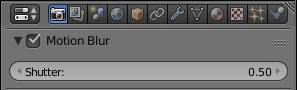
If you are using a real world film camera that takes progressively refined images (usually labeled 1080p), your shutter speed will be 1/50 sec. This loosely correlates to a shutter of 0.5 in the render settings. Setting Blender’s shutter to 1.0 blurs the object by the distance it has traveled during 1 frame. Lower values result in less blur.
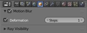
Blender can also use deformation motion blur. The deformation of an object can be produced by modifiers, such as armatures. As well as the regular motion blur, it can be disabled per object in the object tab of the preferences. You can control its quality by increasing the steps. This is important for curved motion blur, because if you sample the face at two frames only a linear motion can be calculated, no matter if the object’s motion is linear or not. For moving motion blur Cycles takes 3 steps, which means if you combine translation as well as rotation on your object, motion blur might not look a hundred percent realistic.
Mist
This option you have to enable in the render layer settings. It will fade out objects in the distance. The further an object is away from the camera the more particles there are to shield it from your view. Those particles are usually water drops in the atmosphere. So if you want to achieve the illusion of a very big scene, you should make your objects fade away in the distance.
The mist rendering is independent of the haze of the , as well as the volume rendering. It utilizes the Z-pass of the camera to determine how far a shading point is away from it. Unfortunately this implies that it does not take into account depth of field or motion blur. You can not natively use the mist in Cycles, what you have to do instead is activate its pass in the render layer settings and then use it in the compositor. It will create a grayscale map, where objects further away from the camera will be lighter. For the settings of the mist, see .
Perspective and Orthographic
The camera can be set either to perspective (default), orthographic or panoramic. The panoramic option is different from the other two, so I will cover it last.
In perspective mode, you can choose the zoom either by entering the focal length in mm, or the field of view. The field of view can be thought of as a cone with the pointy end at the sensor of the camera. If an object is to be seen through the camera, it has to be inside the cone when the angle at the tip of the cone matches the angle of the field of view.
Most photographers are more used to a focal length in mm, so this option is default, increasing the focal length zooms in, while increasing the field of view zooms out. As described above the zoom also depends on the size of the chip.
In the viewport you can toggle between perspective and orthographic view with the number 5 on the numpad. Perspective view is how we or a real camera perceive the world. In orthographic, two objects with the same dimensions will always show equal sizes in the viewport, no matter how far away they are from the camera. Also parallel lines will always be parallel independent from the viewing angle and focal length. Since the size of an object is independent of the distance, moving your camera closer to your scene does not make any difference. Which is why you can adjust the scale of the view. This has the same effect as using your mouse wheel in the viewport.
Depth of Field settings
You can either choose a focal distance, which obviously is relative to the camera’s position, or you can use a focus object, which will cause the focal plane to be at the same point in space, no matter where you move the camera. This is usually more precise and convenient, because you don’t need to refocus every time you move the camera, or during an animation. About ⅓ of the depth of field in front of and ⅔ behind the focal plane will appear sharp.
As for the amount of blurring, only the following rules apply in Cycles:
- Aperture size: narrows depth of field
- Distance: widens depth of field
- Sensor size: narrows depth of field
In the Aperture settings, you can choose how to set up the diameter of the opening. The default is radius, where increasing the value increases the opening and thereby the blurring. If you are used to photography, you might want to change the radius to f/stop, because you might be more used to these values. Note that the values are inverse, so increasing the f/stop will actually close the aperture, so higher values mean larger depth of field.
Cycles treats light unbiased, so mostly physically correct. Unfortunately that does not entirely apply for the depth of field. The Cycles defocus blur is dependent on the distance, aperture and sensor size. Although background compression works fine in Blender, the depth of field is not depending on the zoom. So closer camera position increases the narrowness, larger zoom does not. Fortunately though, decreasing the aperture opening in Cycles does not cause less light to reach the sensor, so you can easily counter this effect by decreasing the diameter.
There is a big difference between Gaussian blur and lens blur. In the lens blur, single points in out-of-focus areas get projected onto the sensor as a disc in the same shape as the aperture opening. These discs are called bokeh. The effect is most noticeable on an image with a dark background and bright spots, for example street lamps in front of the night sky. You can choose the number of blades of the aperture as well as their rotation. If you have an aperture with only three blades, the bokeh will be triangular. With five blades the discs will look like a pentagon and so forth.
Hint: You can produce a custom bokeh shape, if you model hole shaped like it into a plane and get is as close to the camera as possible without getting it clipped. It will be so blurred out that you don’t see it, but the bokehs will have that shape. Unfortunately this trick will produce a very strong vignette.
Panoramic Renderings
Cycles offers three different modes of panoramic rendering. Fisheye equidistant, fisheye equisolid and equirectangular.
In this mode the OpenGL viewport camera does not show the same frame as in render. However you can preview your rendering correctly if you set the display method to rendered (SHIFT + Z).
Fisheye lenses
This mode is similar to using lenses with a very short focal length. So why is there a different mode for this, can’t I just set the focal length to something very small? The blender camera only takes into account background compression and magnification (zoom), but not the fact that light actually needs to pass through a lens before hitting the sensor. Since lenses bend the light towards the focal point, straight lines towards the edge of an image do not appear as straight anymore, but rather curvy. This effect is increased, the shorter the focal distance is. Blender uses a perfect lens, so if you are in perspective mode, straight lines will always be straight. Since this effect is not always desirable, to achieve bending, you can set the camera to fisheye. Values below 12mm will cause black edges on your image, because the lens is not able to project such a distortion on a full frame sensor.
Fisheye Equisolid
This simulates a real fisheye lens. The parameters influence it just as they would would with any other lens, with the added bonus of the barrel shaped fisheye distortion.
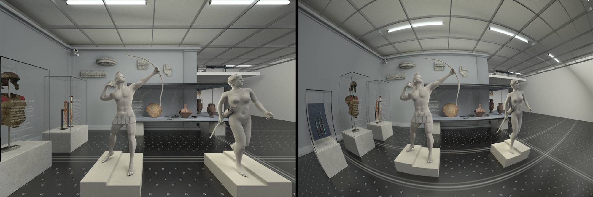
Fig. 13.1) Wide angle rendering. Left: 12mm perspective lens, right: 12mm equisolid fisheye lens. Note how the lines on the ceiling were getting bent more and more, the further they were away from the center. This is the result you would get from a real world fisheye lens, while the left side just looked very distorted towards the edges.
The following two render methods can be used to map the current scene onto the world material of another scene. This way, even with a moving camera, you do not need to rerender background objects for each frame. Also it can be used to match the lighting of the first scene.
Fisheye Equidistant
This mode does not attempt to simulate any real lens, but rather simulates a mirror ball. With a mirror ball you can capture large parts of your environment with a single photo. As the name suggests it is a reflective sphere. So rather than looking at your scene through a lens, the equidistant fisheye lens will look at your scene as if it was reflected by a sphere.
Everything in the field of view will be projected onto an ellipsoid, filling as much as possible of the frame. It will therefore not take into account the chip size. You can choose from a range between 10 and 360°, but only values above 180° deliver sensible results.
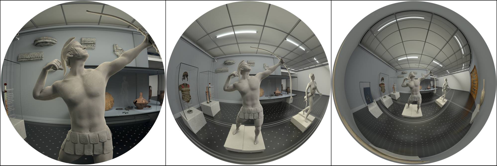
Fig. 13.2) Fisheye Equidistant renderings. From left to right the FoV was set to 90, 180 and 360°. With a FoV of 90° the result is close to an equisolid fisheye lens. 180° can be used to render a skydome, which can be mapped onto a hemisphere. The rightmost one represents a perfect mirrorball, actually featuring a 360° angle. It can be used as an in Cycles.
If you are planning to use the render as background in another scene, be aware that vertical lines might get bent. It is more advisable to use the equirectangular lens.
Mirror Ball
If you are in a hurry or don’t have the patience to shoot a 360° Panorama at the location of your set, you can get a reasonable recreation of the surroundings using a mirror ball. Which is simply a reflective sphere you take a picture of. Many 3D programs can handle mirror ball images, including Cycles. However there is an obvious limitation, the mirrorball is not able to capture anything directly behind it, so you will end up with a smudge in your scene, where that “hole” is. In Cycles the smudge will a small black hole when you map the rendering onto the background of your scene see fig. 13.3. Additionally straight lines get bent a lot. So if the program your porting the panorama rendering to has this option available, I would strongly recommend the equirectangular projection. Since some programs don’t and you can also use mirror balls for matcaps , it is still nice Cycles supports mirror ball rendering.
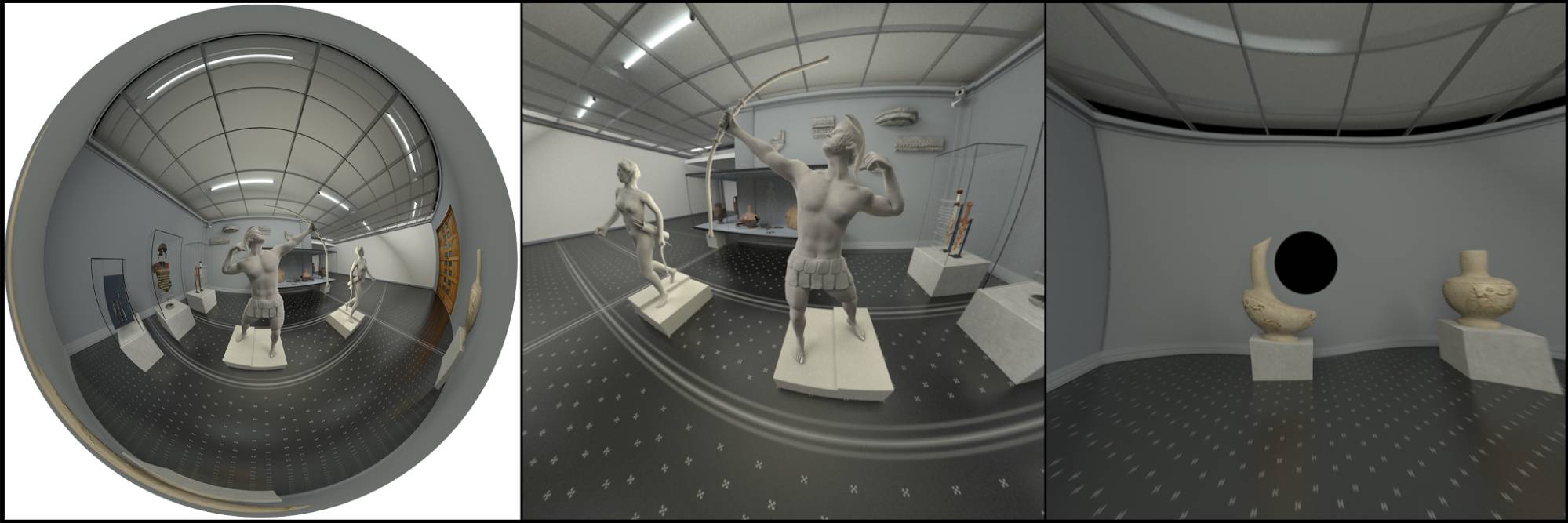
Fig. 13.3) Left: Rendering with the panoramic option set to mirror ball. Middle: Mirrorball mapped to the background of a scene. Right: Mirror Ball projection leaves a small black hole in the environment.
Equirectangular
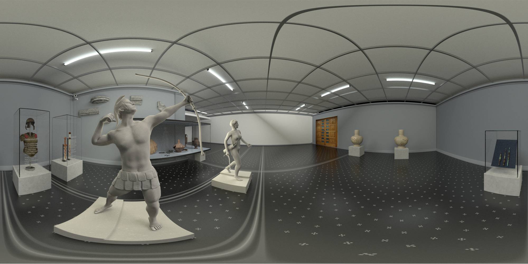
The Equirectangular mode maps your entire scene onto a single image that you then can use as an environment for other renderings or as a reflection map for computer games. You can map the result seamlessly onto any spherical object - including the Cycles world - using the .
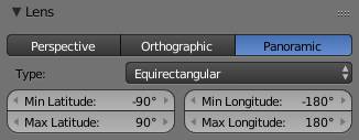
To actually make it work, you have to set up the camera exactly as follows. It has to point along the X axis, meaning its X, Y, Z rotation must be 90°, 0°, -90°. You can still move the camera around in your scene, to determine the location of the sphere, your scene will be projected onto. When you set the camera to equirectangular, the options for the FoV is split into latitude and longitude. The default covers the entire 360° view, but you can reduce that if desired. The aspect ratio between X and Y is commonly set to 2:1.
Fig. 13.4) Equirectangular rendering of a museum scene. If you were to use this image as an environment map, you could either seamlessly project it onto a UV sphere or your world background. The latter is usually used to get the same lighting situation the scene, the picture was taken from, had.
Overview of all Camera Settings
Perspective
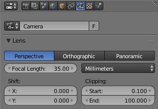
Setting the camera to perspective makes it behave like a real world camera would. In perspective mode, you can choose the zoom either by entering the focal length in mm, or the field of view. Increasing the focal length as well as decreasing the field of view will zoom in.
Orthographic
In orthographic view, two objects with the same dimensions will always show equal sizes in the viewport, no matter how far away they are from the camera. Also parallel lines will always be parallel independent from the viewing angle and focal length.
Hint: To get close to an orthographic view with a perspective camera use a large focal length.
Panoramic
Use this option for fisheye or panoramic renderings with great distortions. You can either mimic a real fisheye lens with the fisheye equisolid settings. Or render a dome projection with the fisheye equidistant. To render a 360° panorama, use equirectangular with the camera pointing along the X axis ( ).
Shift
You can offset the camera from its location horizontally and vertically by using the X and Y shift respectively without changing the perspective. This is similar to lens shift in real cameras. Consider having found the perfect perspective for a short, but you want to change the framing. Camera shift to the rescue!
Clipping
These two values specify what is sometimes referred to as the near and far plane. Since the camera in Blender is not a physical object, it can actually pass through other objects. Since you can’t make an object touch your camera’s sensor without smashing it, there is a natural clipping there, objects or object parts closer to the center of the camera than the distance specified will get clipped. If an object is further away from the camera than the clipping distance, it will also not get rendered. This is important, because if there was no far clipping light rays would have to travel forever until they realize there is no more object to come.
Camera
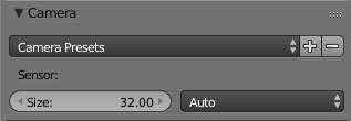
Here you can customize your Cycles camera to fit a real world camera. This is more important when you want to composite a rendering into a photo.
Presets
Under presets you can already choose from a bunch of models, but if the one you were using is not in the list, go online and find out the sensor size and type it into the size field, that should take care of it.
Automatic
In automatic mode, Blender will chose whether the Size corresponds to the width or height of the sensor based on the aspect ratio of the render by selecting width if the aspect ratio is wider than high (landscape) or height in case the aspect ratio is portrait. This corresponds to a photographer rotating his camera 90° for a portrait shot. You can use this setting instead of actually rotating the camera.
Display
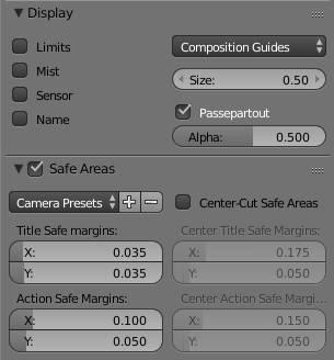
Limits
Displays a yellow cross where the focus plane is.
Mist
Under the render layer settings you can enable mist. This creates a haze that covers up objects dependent on their distance to the camera. The mist has a start and stop distance, enabling mist display will show two dots along the line of the camera direction and color the area in between yellow. In front of the start dot there is no mist and behind the end dot, everything is covered up.
Sensor
Displays the sensor area as a gray dashed rectangle - only in camera view. The area shows the difference between the camera field of view and the sensor’s x to y ratio.
Name
Enabling name will display the camera’s object name at the bottom left side in camera view.
Safe Area
This was more important for old TVs that would use letterbox for displaying or simply crop 16:9 images. Back then sometimes the edges of the movie get cropped, and in case of subtitles, so generally you will try to keep the important parts inside a frame that is safe from getting cut. This is why there is a safe or title safe area of a picture.
Composition Guides
There are some general rules for compositing images, you can display the division of the frame based on the corresponding rules in dashed lines from the dropdown. The lines will be displayed on top of everything else.
Center
Displays two lines, one in X and one in Y that meet at the center of the image seen through the camera.
Center Diagonal
Displays the two diagonals of the image seen through the camera. They meet in the center.
Thirds
One composition guideline is the rule of thirds, where rather than placing an object in the center of the frame, you place it at around one third to either the left or the right. This option divides the image seen through the camera into 9 equal pieces, 3 in X by 3 in Y.
Golden Section
The golden section has fascinated mathematicians, painters and photographers and many others for at least 2.400 years ( Mario Livio 2002, The Golden Ratio, Broadway Books ). When used in a composition, it is said to be aesthetically pleasing.
The golden ratio is  .
.
You can display the golden sections with the following options:
Golden
Displays the golden section in rectangles
Golden Triangle A
Displays the golden section in triangles, where frame is intersected by the diagonal going from top right to bottom left. There are two more lines coming from each free corner and meeting the opposite sides at an angle.
Golden Triangle B
Displays the golden section in triangles, where frame is intersected by the diagonal going from top left to bottom right. There are two more lines coming from each free corner and meeting the opposite sides at an angle.
Harmonic Triangle A
There is only little difference between harmonic triangle and golden triangle. It is based on Leibnitz’ work, which would be too much to put into this book.
The option in the Cycles camera displays a diagonal line from top right to bottom left and two smaller lines coming from the other corners but meeting the sides at slightly different angles than the golden triangle does.
Harmonic Triangle B
The option in the Cycles camera displays a diagonal line from top left to bottom right and two smaller lines coming from the other corners but meeting the sides at slightly different angles than the golden triangle does.
Size
With this value you can control the camera’s size in the viewport.
Passepartout
This originally describes a piece of paper that does not let anything shine through it. It is commonly used for framed images to center the focus on the image, or fit an image into a frame with different dimensions.
In Blender it means that, when looking through the camera in the viewport, you can blend out whatever will not seen through the camera in render, the alpha slider below it determines how much it is darkened.
Hint: To actually keep that part from being rendered in render preview mode, use the border option in the render settings.
Depth of Field
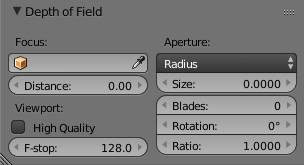
Focus
You can either choose a focal distance, which obviously is relative to the camera’s position, or you can use a focus object, which will cause the focal plane to be at the origin of that object, no matter where you move the camera. You can either select an object from the dropdown menu or use the eyedropper which allows you to select an object from the viewport. Choosing a focus object will override the distance settings.
The Distance field allows you to set a focal distance directly. Hovering over it and hitting the shortcut ‘E’ will create an eyedropper that allows you to select the distance directly by clicking on any surface in the viewport. Clicking and holding down the mouse will show you the distance directly (fig. 13.5).
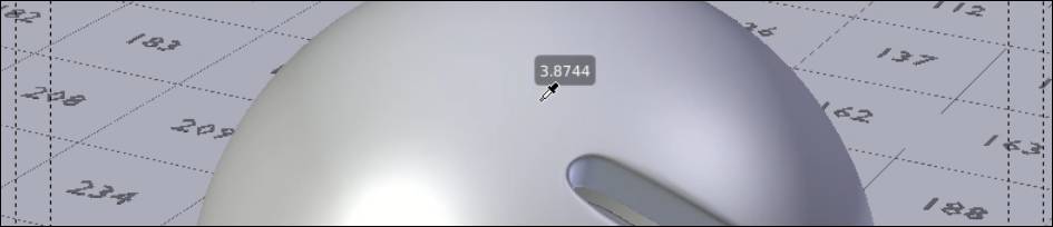
Fig. 13.5) When hovering over the distance field in the depth of field settings and hitting the key “E”, an eyedropper appears. You can hover over any geometry in the scene and left-click to set the distance in the DoF settings to exactly the distance from that point to the camera. When clicking and dragging with the mouse, a small number field appears above the cursor showing you the distance that will go into the DoF box when you release the mouse.
Aperture
You can influence what is in focus by altering the diameter of the aperture. By default you can enter the size opening or specify an f/stop. Bigger size means that the diameter gets better which means more defocus while for f-stop a lower value results in more defocus since increasing the size of the f/stop actually closes the aperture, because the values represent the inverse of the diameter.
Blades
In out-of-focus areas, what is just a point in your scene gets projected onto the sensor as a disc, called a bokeh. The shape of the bokeh is dependent of the shape of the aperture. Choosing how many blades the aperture has determines how many corners the bokeh disks have. Leaving this at 0 will make them round. If you are using non-round bokehs, you can rotate them, using the rotation slider.
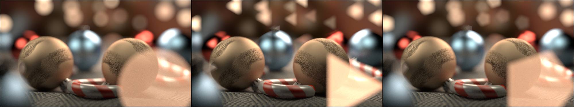
Fig. 13.6) Image with shallow DoF and bright light sources in both fore- and background. Left: 0 blades. Middle: 3 blades. Right: 5 blades. The starrish look of 5-blade-bokeh adds to the christmas feeling.
Ratio
You can simulate an anamorphic lens by using the ratio. A value below 1 will squash the bokeh, while values above 1 will stretch it. Unfortunately you will not automatically get the famous lens flares a real world achromat produces.
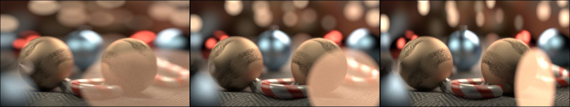
Fig. 13.7) Image with shallow DoF and bright light sources in both fore- and background.
Left: Ratio 0.5 (very uncommon in the real world).
Middle: Ration 1.0 (the default).
Right: Ratio 2.0, a value common for real world achromatic lenses.

