10: The Grounded Grid Amplifier
The use of the grounded grid amplifier using triode valves (Fig 10.1) is a popular
topology for many different operating frequencies. A triode valve when configured as a grounded cathode amplifier suffers from one major drawback. The inherent large capacitance (Cag) that exists between the anode and grid causes unwanted feedback of signal. If it is of the correct phase this will cause the valve to oscillate. To prevent this, grounding the grid and using the cathode as the input terminal solves the problem in 90% of cases. There is always some other mechanism that can cause feedback, so generally the physical construction of the amplifier is designed in such a way to minimise this.
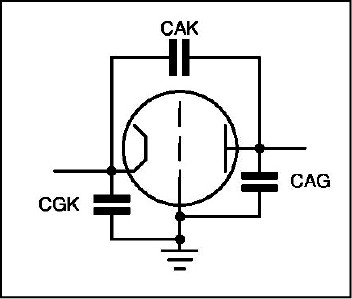
Fig 10.1: Grounded grid topology.
Potential Gain
The cathode driven valve has a much lower potential gain than a grounded cathode grid driven amplifier. This is because the input and output currents are in phase, whereas in the grid driven amplifier they are 180º out of phase. The cathode current flowing to ground through the input network impedance is resisting the input drive signal. The result is that the impedance seen by the driving source is now very low. The current being in phase forms a type of negative feedback signal and this to some extent enhances the linearity.
In the grid driven amplifier the driver is presented with relatively high impedance and hence can develop a large grid-cathode voltage swing requiring little drive power. The cathode driven amplifier requires a much higher drive power to obtain the same grid-cathode voltage swing. The gain criterion is the RF output power versus the RF input power, so the gain is lower when cathode driven – often very much lower!
The transconductance, however, is the same whether the valve is grid driven or cathode driven. Where high gain is required the grid driven amplifier is the best option. This often needs external neutralising components to counter the internal feedback signal caused by the anode to grid capacitance. Very often the lower gain can be useful.
A grounded grid amplifier is inherently more stable, and the cathode as an input terminal is closer to 50Ω than a grid driven amplifier. For HF linear amplifiers the driver is normally a transceiver having an output power of around 100W PEP. If the grid driven amplifier were chosen the drive power needed would be a small fraction of this amount. Theoretically, a grounded cathode (grid driven) triode amplifier, when not driven into grid current, requires zero driving power; it only has to develop the voltage swing into high impedance.
A grounded grid amplifier therefore better suits 100W PEP transceivers as the power required to drive it is nearer to 100W PEP.
Biasing
In grounded grid topology the cathode returns to ground via an input resonant network which can be RF grounded at the bottom end. The grid is at 0V relative to the power supply and the bias voltage, if required, means that the cathode needs to be lifted above ground by the required voltage to obtain the correct biasing point. If the triode requires, for example, –20V grid-cathode to establish the correct operating condition, it means the cathode needs to be raised above ground so that it is now at +20V. In other words it is the same as a cathode biased amplifier with a resistor in the cathode to ground.
In small signal Class A amplifiers drawing a relatively constant current this method can work but, for a power triode where the idle current is fairly low but the peak anode current can be high, a simple resistor bias scheme will not work. If the bias is +20V to get the required idle current of, say, 50mA but the anode current peaks at 400mA the voltage drop across the resistor will be eight times higher when the anode current is driven fully. If the idle point is +20V the full anode current will generate a bias voltage of +160V. This is the same as –160V grid-cathode and will totally cut off the conduction. So a different method has to be used and this is shown in Fig 10.2.
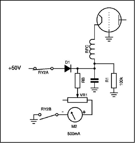
Fig 10.2: Cathode resistor biasing.
The cathode current flows to ground via RB and VR1. The RF signal is isolated from the bias components by an RF choke and decoupled to ground by a low reactance capacitor. Adjusting VR1 sets the quiescent cathode voltage and hence the grid-cathode voltage. To cut-off the valve during receiving periods, two relay contacts are used which are controlled by the PTT line. On transmit RY2B is closed and RY2A is open and the cathode current flows to ground via the meter M2. On receive the relay contacts reverse and the +50V cut-off voltage pulls the cathode up to this value, hence biasing off the valve. Resistor R1 is a safety device in case the +50V supply or RY2A fails; the cathode voltage will float up to a high voltage and cut-off the valve.
Constant Voltage Biasing
If the cathode network, instead of being returned to the supply 0V rail, is connected via a circuit to maintain a constant +20V between ground and the cathode we have the ideal solution. This could be a simple Zener diode regulator as shown in Fig 10.3. As the anode current varies the current through the Zener also varies, but it remains constant at +20V. It requires quite a high power Zener diode to make it work when the anode current is high.
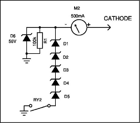
Fig 10.3: Zener cathode biasing method.
In Fig 10.3 the cathode biasing is performed by several high power zener diodes connected in series to obtain the correct voltage. The cut-off biasing is supplied by a lower power Zener D6, which is selected to be above the minimum cathode voltage to cut-off the valve.
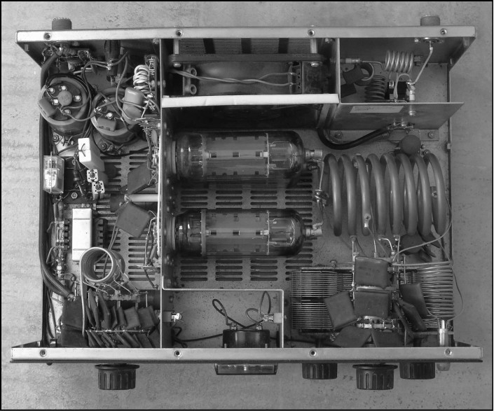
Grounded grid amplifier using TV sweep tubes.
Often a high power quasi-Zener constant voltage shunt regulator is used. This behaves as a normal Zener diode but can handle very high peak cathode currents. Normally we need to adjust the bias voltage to set the required idle current, and as all valves vary a bit this voltage needs to be adjustable over a range. A suitable circuit is shown in Fig 10.4.
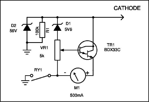
Fig 10.4: Adjustable cathode shunt stabiliser circuit.
The cathode bypass is connected to the collector of an NPN Darlington transistor. This transistor has the cathode current meter in the emitter line and a relay contact. The relay is operated by the PTT control line so it is open on receive and closed on transmit. The base of TR1 is biased by a Zener diode and a low value potentiometer to set the required collector voltage. Across the collector to ground a high value Zener and a high value resistor in parallel are used for cut-off biasing when the PTT relay is open. All the cathode current flows to ground through TR1 and the current meter. The meter indicates the anode current plus any grid current. The circuit will hold the set bias voltage constant between a few milliamps and 1A peak current. The value of the 5V6 Zener sets the minimum bias voltage and will require selecting to suit the valve in use.
Zero Bias Triodes
Several triodes have been developed which eliminate the need for bias circuitry. These include the 811, 572B and the 3-500Z and are attractive as they simplify the amplifier design. The only problem is that the valve still needs to be cut-off during receive, which requires a high positive cathode voltage or a high negative voltage on the grid. If the grid is used to feed in the cut-off bias it has to be lifted off the DC ground and decoupled with low inductance capacitors. If the decoupling capacitor has significant inductance it can re-introduce instability as the grid is no longer properly grounded. The other potential problem is that if a flashover occurs it can wipe out the decoupling capacitors and leave the grid floating. It will then oscillate, violently destroying itself.
Although the popular zero bias triodes are simpler to use for biasing they generally have directly heated cathodes. This means that the heater current and the RF input signal have to be handled correctly (in an indirectly heated cathode the design is easier as little or no inter-reaction occurs). This means that the filament current has to be fed into the cathode by high current RF chokes, which are a source of problems. It also means that the two ends of the heater must be solidly connected together with a low reactance capacitor to ensure they are both at the same RF potential.
A typical grounded grid amplifier input circuit is shown in Fig 10.5.
Fig 10.5: Typical zero bias grounded grid amplifier input circuit.
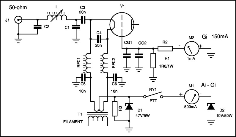
The input signal is transformed to the cathode impedance by the pi network C1, C2 and L. This passes via a DC blocking capacitor C3 to the cathode terminal. This capacitor (and C4) is made up from two 10nF capacitors in parallel to handle the high RF current flowing. The heater current is fed via two ferrite wound high current chokes RFC1 and RFC2. The heater secondary winding is supplied by transformer T1, and the winding is centre tapped. The grid is floated above ground by decoupling capacitors CG1 and CG2 and allows the monitoring of the grid current with meter M2. The full-scale deflection is set by resistor R1 and R2 to suit the meter sensitivity. Cut-off bias is provided by Zener diode D1 and the PTT relay RY1. On transmit the PTT relay switches to ground via the cathode current meter M1.
The anode pi tank circuit is identical to any other type of amplifier so it hasn’t been included. If the amplifier has to cover several bands input networks need to be provided for each band, which need selecting by a band switch arrangement.
Cathode input network
In some simple grounded grid amplifiers there is no attempt made to produce a low SWR match to the driving source. This is often a source of undue distortion. The preferred method is to use an impedance matching network to transform from the driving source to the cathode. However, this is not as simple as it seems. There has been a great deal of confusion and erroneous statement on this topic and it is perhaps necessary to see what the experts had to say on this matter.
William (Bill) Orr, W6SAI, was a senior design engineer in the Eitel-McCullough Valve Company, which we also know as Eimac. W6SAI was the editor of a popular regular newsletter called Amateur Service (AS) published by Eimac for amateurs. In AS-3 bulletin some pertinent details are given on grounded grid amplifiers. An expanded version was also published in QST in August 1961 with the co-writers Ray Rinaudo, W6KEV, and Robert Sutherland, W6UOV, also Eimac engineers. This also appears in the ARRL book Single Side Band for Radio Amateurs. In this era there were no solid-state transmitters, so the information purely reflects that for valve transmitters / exciters. As we will see later the solid-state transmitters are a major problem for this type of amplifier.
Bill Orr has this to say about grounded grid amplifiers: “Any single-ended Class B stage (regardless of the tube used) draws grid and plate current over only a portion of the operating cycle (approximately 180º). The input impedance of such a stage, therefore, does not represent a constant load. The waveform delivered by the exciter to the grounded grid stage is greatly distorted over the portion of the cycle that the amplifier draws grid and plate current. Although published ‘input impedance’ values may look attractive, they actually represent only the fundamental component of input impedance (useful for tank circuit ‘Q’ calculations). Since the input load impedance of the Class B grounded grid stage is not a constant value, it is necessary to transform it to a constant impedance which will resemble 50Ω over the complete operating cycle. This is best done by a high C tuned circuit placed directly at the cathode of the grounded grid stage.”
The implication of this statement is that it is not considered good practice to simply connect the output of a 50Ω driving stage to the cathode through a simple DC blocking capacitor. The result will be gross distortion of the input signal and this will simply be amplified to become an even bigger distorted signal at the output. The other thing, which is perhaps not obvious from Bill Orr’s statement, is that he was referring to a constant power level drive into the amplifier and observing the sinusoidal RF waveform distortion at that fixed level of drive. And that is where most of the erroneous facts have arisen. It is not possible to devise a simple matching network that will always match the 50Ω impedance of the exciter when the cathode impedance varies over such a wide range. For some reason it became urban legend that one simple network can fix all the ailments of the grounded grid amplifier. Having measured the impedance swing on several different valves at different drive levels I can tell you now that it is impossible to make a network such as this.
One example will serve to illustrate the problem of valve impedence swing. Some years ago I constructed a 6m linear using the Russian GI7-BT triodes and needed to establish the cathode impedance over the working drive range. This data wasn’t included in the data sheet so I had to determine it experimentally. A test amplifier was built and driven by a very good high power driving source made by Hewlett Packard and a dual directional coupler was used to sample the amplitude and phase of the input signal. From this I was able to measure the impedance as the drive was varied. At 1W drive the cathode exhibited an impedance of over 600Ω and the grid current was very low. At 5W the impedance was 150Ω and the grid current was 50% of the safe maximum according to the data sheet. At 10W the grid current had reached the maximum value, with an impedance of under 30Ω.
The use of a resonant tank circuit at the cathode provides the flywheel effect and this restores the carrier waveform back to a true sinusoidal shape. From measurements made in the Eimac laboratory on various valve types they showed that no matter what type of valve was used they all performed better with the cathode network than without it. Generally, an improvement in output power of some 5% was achieved with less driving power and lower IMD values. It also showed that the matching to the exciter was less critical and did not need specific lengths of coax between the exciter and the amplifier to obtain a good low SWR match. However, all the tests were made with a very high quality Class A high power driver, which was heavily damped with resistive loading, and it was largely immune to mismatch effects. An average SSB transmitter, which wasn’t named in the report, when substituted as the exciter was noted to be inferior to the special driver stage. This was for valve equipment as the exciter or driving source.
Solid-state drivers and grounded grid amplifiers
If we fast-forward about 50 years, all the modern HF transceivers are solid-state and these are completely different in the way they handle mismatched loads. They can be extremely sensitive to mismatching and particularly reactive loads. The earlier valve exciters, with a pi tank and a couple of 6146 valves, didn’t feel a thing when a poor load was connected. The operator could adjust the anode tune and load capacitors to compensate for the reactive load of the antenna, as long as the SWR was not too high. Often, an SWR as high as 3:1 could be happily matched, and in some cases up to 5:1. If the antenna SWR is higher than that, a normal ATU would sort out the problem with little fuss.
Modern day solid-state transmitters are at a severe disadvantage when it comes to driving grounded grid amplifiers, because the amplifier presents a load that is varying over a wide range as the power level varies. Although they often have an ATU built in, this is of no help.
If the mode used is AM then to some extent the problem is alleviated as the impedance does not vary by such a large amount, because the constant carrier level causes the cathode impedance to be more constant. But SSB varies from zero drive power up to peak value.
An antenna that is mismatched can be made to look like a good 50Ω load by the ATU, so the transceiver is happy. But the grounded grid amplifier input impedance does not behave like an antenna. The antenna’s SWR is constant, no matter what the power level is. The grounded grid amplifier impedance varies from almost an open circuit at very low drive levels and as the drive is increased it begins to fall to a lower level. When the valve starts to draw heavy grid current the impedance drops to a very low value. At a very specific drive level it will approach a near perfect match at 50Ω, if the input network has been set up correctly, but it only occurs at that particular drive level. As one amplifier designer once commented about the match changing with drive, “It’s like trying to hit a clay pigeon in flight. The darn thing is always moving!”
And that is the problem with the solid-state transceivers we have today. The ATU can compensate for static antenna mismatch condition but it cannot vary its matching to follow the power level when it is constantly changing.
Cures for cathode impedance variation
Many and varied have been the attempts to stabilise the input impedance of the grounded grid amplifier. If we compare the grid driven and cathode driven amplifier topology we can see a possible fix to the problem.
A popular method of providing constant input impedance for the grid driven (grounded cathode) topology is to dispense with the tuned circuit and to substitute a low inductance load resistor. If this resistor is chosen to be ~50Ω and the exciter is connected directly to it via a DC blocking capacitor so that it doesn’t upset the biasing condition, the exciter is effectively supplying a dummy load. The grid voltage swing is purely a function of the RF driving power. This technique is commonly called a passive grid network.
The passive grid input method is attractive as it eliminates the tuning components needed for each band and it allows operation on any frequency needed. The anode network of course cannot be treated in the same way and the coverage is purely limited by the anode network. The disadvantage of the passive grid network is that it needs a much higher driving power to obtain the required grid-cathode voltage swing. However, with a 100W PEP driver this isn’t normally a problem. It needs most of the exciter’s available output power to drive the valve to full output and as such it means we don’t need to find a way of reducing the drive power very much. The grid resistor, of course, dissipates high power so it needs to be correctly chosen. The grounded grid and the passive grid amplifier need about the same drive power, hence it also has a low potential gain.
I was involved in a design problem some years back for a military frequency-hopping radio system. When hopping over a wide band of frequencies it is impossible to make an antenna that presents a low SWR at all frequencies and still radiate efficiently. (Some wide-band antennas which appear to have low SWR over considerable bandwidth are due to loading resistors to absorb the mismatched power and as such they only radiate a portion of the power fed into them, in some cases as little as 30%.) The only item that has a constantly low SWR is a dummy load! We attempted to make an adaptive ATU that would always present a reasonably low SWR to the transmitter and we actually managed to get close to a workable system after about two years of effort. But the hop speed was only four hops per second. The user required a speed of 50 hops per second and that wasn’t anywhere near possible.
In the case of the grid driven amplifier, the drive level can be significantly reduced by using a broadband transformer to step-up the impedance from the driver to the grid. If a 4:1 transformer is used the 50Ω of the exciter is transformed up to 200Ω and the drive voltage is doubled. This is a good fix if you only have a 10 or 20W transmitter, but unfortunately it won’t work for the grounded grid amplifier.
This fix was used in one linear amplifier made by Heathkit. In the SB-230 linear
(Fig 10.6) Heathkit uses the Eimac 8873 conduction-cooled, grounded-grid triode. The cathode input circuit is a pure passive network with a bank of resistors paralleled to provide a 100Ω dummy load connected in shunt across the cathode to ground. The 8873 input impedance starts out as almost an open circuit at low drive levels and gradually falls to about 100Ω at the maximum grid current rating. Hence, the two loads equate to a 50Ω load at full drive and a 100Ω load at minimum drive levels. It has an input SWR which is about 2:1 worst case and close to 1:1 at full drive. This suits the modern solid-state exciter better. The downside is that it needs only about 50W PEP to drive the amplifier to the full output of about 600W. (Eimac gives a figure of 26W to achieve 587W output at 30 MHz. As the dummy load absorbs about half the drive power this doubles the drive level required.) Consequently it is susceptible to over-driving by an inexperienced operator.
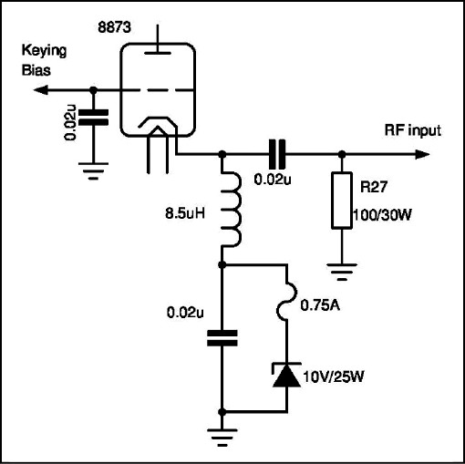
Fig 10.6: Heathkit SB-230 cathode input network.
The cathode shunt resistor is rated at 30W and consists of many paralleled 2W carbon-composition resistors mounted on a tag strip board. The resistor is made from 15 x 1.5kΩ wired in parallel. These have a reputation of being too low a power rating and often they go higher in resistance due to over heating. Many amateurs have replaced the original 2W carbon composition resistors with more appropriate 3W metal-film resistors in an effort to gain some extra dissipation. The basic problem, however, is that the operator is not taking sufficient care with the drive level, and they often do not have the ALC hooked up to the transceiver. The 8873 valve needs at most ~40W to drive it into saturation on the lower HF bands and the typical 100W PEP transceiver simply has too much power.
A better method today would be a thin-film encapsulated heat sinkable resistor such as the types made for snubber resistors in switch-mode power supplies. These are available in up to 500W dissipation and are low inductance. A TO-220 packaged type is rated at 50W dissipation and 100Ω is a very common value for snubber resistors. Some of these resistors will work happily up to at least 1GHz and exhibit close to zero inductance at that frequency.
A comprehensive cure for the SB-230 would be to insert a power attenuator between the input and the cathode to dissipate the excess drive power and to stabilise the input Z. A 3dB/50W attenuator would be appropriate, with the ALC hooked to the transceiver to control the absolute drive level.
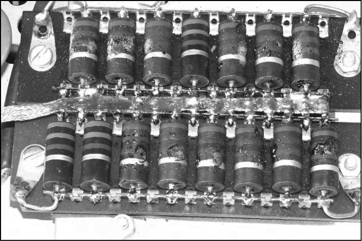
Heathkit SB-230 cathode resistor array, showing typical damage that can be caused by over-driving (photo: Rad, ZS6RAD).
Instability problems
Although connecting the valve in grounded grid radically reduces the effective value of the anode to grid feedback mechanism it does not entirely eliminate it. The output capacitance of a grounded grid valve is in fact the capacitor shown as Cag in Fig 10.1. This is also true for a screen grid valve; the output capacitance is between the anode and the screen grid. Hence, if the RF grounding of the grid is not 100% effective the large circulating output current flowing in this interface will cause a corresponding RF voltage to appear across the grid-cathode interface. If the grid is DC grounded this normally provides sufficiently low impedance to prevent feedback.
In some UHF and microwave triodes the potential gain can be very high at lower frequencies. Although the effective value of Cag is low, it is not zero. If we calculate the reactance of the value of Cag at different frequencies we can see the potential problem.
The Eimac 8873 triode is a fairly delicate (and expensive) valve. The maximum grid dissipation is only 5W, the maximum anode dissipation is only 200W. The 8874 and 8875, which are electrically identical and only differ in the anode cooling method, have an anode dissipation of 400W and 300W respectively. The 8873 is hence not much better than a single 572B. A replacement valve – if you are able to find one, as they haven’t been made for years – is not going to be cheap. Current prices (2017) are around $400 to $600 for genuine Eimac NOS valves. Stay well clear of used valves!
Effect of anode-grid feedback capacitance
Assume that the valve is operated at some low frequency such as 80m. The value of Cag for a triode such as the 3-500Z when operated in grounded grid is given as 0.07pF in the Eimac data sheet. The grid-anode capacitance is 4.7pF. In grounded cathode operation the value of Cag is hence 4.7pF and the output capacitance of the valve alone is hence 0.07pF. The two capacitors swap positions when the topology is changed. The grid-cathode capacitance stays the same at 8.3pF no matter which topology is used.
At 3.5MHz the reactance of a 0.07pF capacitor is very high, it is about 650kΩ, which is pretty insignificant. However, we should not lose sight of the fact that the valve internal capacitance is not the only possible source of feedback around the valve. The valve will be mounted in a socket and it is in close proximity to the metalwork which houses it. High ground currents exist in some parts of the metal chassis and if this has a high skin effect resistance the large currents induce voltages into other parts of the amplifier circuitry.
A classic feedback mechanism is via the anode tank coil. Very often this is mounted close to the vertical walls of the anode compartment. Two factors come into play. If the coil is mounted less than about two coil diameters away from a conducting metal surface considerable eddy currents flow in this metal. This behaves as a shorted turn coil and it severely ‘de-Qs’ the coil, leading to higher loss and lower output power. The eddy currents are large currents flowing within the metal and they induce voltages in other parts of the amplifier chassis by magnetic coupling, similar to transformer primary and secondary windings. If not prevented or well controlled this can lead to problems.
Some amateur amplifiers are built using plated steel chassis, due to penny pinching by the manufacturers, and they exhibit weird ground loop effects. One particular model has a bad reputation of being almost impossible to tame because of this choice of material. It needs big copper bonding straps to completely tame the amplifier. A corresponding amplifier made by another manufacturer, using the same valves, has an almost identical physical layout and this amplifier does not suffer from the same problems. This amplifier uses an aluminium chassis.
These two extra factors can radically increase the effective anode-grid feedback. If the valve grid terminal varies in voltage due to the applied high anode current flowing it can cause instability. Very often the grounding straps for the grid pins introduce some inductance and these are also capable of providing the necessary feedback signal to start oscillation.
The basic rules to ensure oscillation are well understood. Two major criteria need to be satisfied: first, the gain of the device has to be greater than 1 and second the feedback signal has to be in phase with the input signal. If both of these criteria are met the device will oscillate at some frequency, determined by the inductance and capacitance in the circuit.
Very often the valve will not oscillate at the operating frequency, but at some other frequency where the grounding straps and self and stray capacitance satisfy a resonant effect. In most cases the frequency where this occurs is much higher than the frequency that the amplifier is designed for, and often in the VHF region.
Parasitic oscillation
These spurious oscillations are commonly known as parasitic oscillations and can be a serious problem for some valve types. If we examine the characteristics of a typical valve, the Eimac 3-500Z, we find that Eimac gives operating conditions for up to 110MHz at near full output. All devices tend to fall off in gain as the frequency increases. In semiconductors we have a factor called fmax, which is the frequency where the gain has fallen to 1. Any frequency above fmax is incapable of sustaining oscillation. Valves are not generally rated in this way but it can be inferred in most cases, if not stated on the data sheet. For example, the Russian GI-7BT triode in the data sheet gives power output ratings for CW and self-excited pulsed operation. At 18.5cm wavelength (1.6GHz) it is rated at a minimum of 40W output and at 10cm (3GHz) under pulsed duty it is rated at 12kW for 3µs pulse length. (Incidentally, under self-excited pulse operation it is pulsed with an anode supply of 9kV and it draws 7.5A cathode current, so it is quite a feisty valve.) Hence, we can estimate it will still have some useful gain at 6GHz as a normal amplifier and probably higher. The fmax of the 3-500Z triode is probably about 500MHz, judging by the characteristics, so anywhere up to that frequency it could experience parasitic oscillation problems.
Parasitic oscillations are not exclusively a problem with just grounded grid circuits. One of the primary reasons for choosing grounded grid is because it does not normally need neutralising, but there are always exceptions to the rule. Some of the worst amplifiers with parasitic effects are the grounded gird types, simply because there is no neutralising adjustment to correct the effect.
Any amplifier, if the circuit conditions allow it, can suffer from this problem. Generally, parasitic oscillations can be reduced or completely eliminated by the use of anti parasitic chokes (APCs) which are fitted at the anode and other terminals to discourage the unwanted resonant effects. In many cases this is simply a low value inductor shunted by a low value resistor to de-Q the circuit. They are fitted as close to the terminal as possible with zero lead length. A picture of a typical APC for a 6146 anode is shown above. The 2W carbon-composition resistor normally used suffers from the high temperature they are exposed to and over a period go higher in value. In low power applications a suitable APC is a 5W wire-wound resistor of about 22Ω to 47Ω. This eliminates winding an inductor as the resistance wire forms the inductor. The wire-wound resistor is superior to the normal technique as it can withstand the high temperature better and the cost is lower.
The other factor to be aware of is that although the manufacturer in the data sheet give the inter-electrode capacitance values, these measurements are made at a low frequency for ease of obtaining an accurate measurement. They are generally performed on a cold valve in a special shielded fixture to minimise stray capacity effects. It cannot be assumed that these capacitance values hold true for higher frequencies. The internal wires supporting the various parts of the valve are used to carry the currents within the structure and exit the base for the connections. Any wire, if it is relatively long and thin, has significant inductance. At some high frequency, with the inter-electrode capacitance, it will resonate.
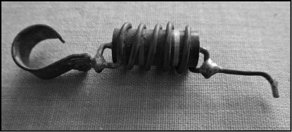
Anti parasitic choke for anode of 6146 valve.
RF Choke problems
When an amplifier is designed it is imperative to examine each and every component selected very carefully to determine if it has any unwanted spurious resonant properties. This is particularly important for any RF chokes used to feed in supply currents. In the classic grounded grid amplifier using zero bias triodes the area which often causes problems is the filament chokes as these carry high current and are connected in shunt with the input signal. These can also be source of loss and absorb a fair amount of the drive power if incorrectly chosen. If the temperature of the choke exceeds the Curie temperature of the ferrite material the inductance falls to a very low value.
The type of choke that suffers the most problems is the bifilar wound variety as both windings are on a common ferrite rod. It should not be overlooked that inductors, when connected in parallel, have a lower net inductance: they behave as resistors in parallel. Hence, each choke needs to be twice the inductance required when in circuit and paralleled up. With the bifilar choke it also has twice the heating effect compared with a pair of individual chokes because the same heater current flows in each winding. The magnetic saturation from the heater current is also twice as high. This can push the choke over the cliff with less temperature rise.
The other most significant RF choke is the anode feed choke in the normal pi tank network. This is common to all amplifiers of this type, whether grounded grid or other circuit topologies. The anode RF choke has to withstand a very high RF voltage and also carry a substantial amount of DC to feed the anode. The inductance of this choke has to be high enough to prevent, or at least reduce to a low value, the AC current flowing to ground that is induced by the high RF voltage across the anode to ground.
When coupled in parallel with the anode to ground capacitance the choke inductance can be brought to parallel resonance so that it appears to behave as a very high value resistance to ground. In a single band amplifier this is simple to arrange. However, in a multi-band HF amplifier this is almost impossible to achieve for every fitted band. Consequently it is often found that a high loss occurs in this component on the lower frequency bands and the heat generated causes problems. In many cases when inspecting an amplifier the enamel wire used to wind the choke is discoloured, and sometimes completely burnt away in places. If the adjacent turns short together the loss rises dramatically and a burn up usually occurs, rendering the choke irreparably damaged.
As an experiment, an Eimac 4CX250 valve was set up in a SK-600 socket and connected to a Vector Network Analyser to measure the effect. An SMA RF connector was fitted to the base and a short, wide copper strap connected the centre pin of the RF connector to the grid terminal. The data sheet value of the grid-cathode capacitance is about 16pF, measured at 1MHz. The reactance of a 16pF capacitor at 144MHz is ~68Ω and the VNA should indicate this value. However, the value measured was radically different. The effective value was calculated from the R and X values displayed. At 144MHz the effective capacitance had dropped to about 8pF, showing that the internal lead inductance was having an effect. When measured at 432MHz the grid-cathode was no longer behaving as a capacitor, it had gone through the resonant frequency and was inductive. The measurement was repeated with the heater powered up and some change occurred but it was not really much different. This shows that one can never assume that the data sheet values are constant with frequency.
Can I use any valve in grounded grid?
That is a good question and again there has been a lot of controversy on this topic. Bill Orr, W6SAI, and his colleagues at Eimac issued an engineering bulletin on the subject. In it they stated that some tubes were not suitable for operation in grounded grid. These tubes have high perveance grid structures and due to their construction can be damaged by the high grid current when operated in cathode driven circuits. They went on to list the various tubes which must not be used in grounded grid: included in these were the 4X150 and its variants. People took notice and accepted this as the true state of affairs.
But then it gets interesting. Not long after, Eimac issued another bulletin on the subject in which they appeared to do a complete about face. They now stated that it was acceptable to operate some of the high perveance tubes in grounded grid, and they specifically mentioned the 4X150, as long as the circuit was arranged in a particular way. The fix apparently is to RF ground the control grid and screen grid with low inductance capacitors and to feed the DC supplies to these grids. This, they claimed, alleviated the high grid current problem. The previous method was to DC ground the control grid and to raise the cathode DC voltage to obtain the correct biasing point. For the 4X150 that required about +50V cathode to ground for Class B operation. To compensate for the cathode being lifted 50V positive meant that the screen grid also needed to go up by +50V, to keep the correct screen grid-cathode potential to restore the gain lost.
But it didn’t stop there. A year or two later they issued yet another engineering bulletin where they reverted back to opinion number one, in which they stated that grid current of any significant magnitude is not a good thing and grounded grid is not recommended. Perhaps they had a lot of warranty claims due to failed tubes – we will never know.
Confused?
Being able to piece together the history almost 50 years later, it seems clear that Eimac or the new company that emerged hasn’t as yet changed their opinion on the matter. So the tubes listed are still, according to the experts, not recommended to be used in grounded grid.
At the time the state of confusion was amazing! Fights almost broke out on the subject and ‘Walter’ was totally bewildered and stunned: can he or can’t he? Nobody could give him a definite answer. One group waved around bulletin Number 1, only to be shot down by another group who presented bulletin Number 2 as evidence, and yet another group had managed to get hold of a copy of bulletin Number 3.
A similar bun fight arose over the cooling method that Dick Knadle, K2RIW, showed for his 70cm amplifier using the 4CX250B. Instead of blowing the cooling air up through the air flow socket from the grid compartment, which prior to his amplifier was the accepted method of cooling, he instead pressurised the anode compartment, threw away the SK-606 ceramic chimneys and fitted PTFE tubes to duct the air out of the anode box.
Initially, Eimac had serious reservations on this technique and gave it a big thumbs down. However, they then seemed to have had a change of opinion and stated that having done some further testing with this method they were happy to accept it as a way of cooling the 4CX250B series. They stopped short of recommending it, they simply said there was no compelling evidence to say that it shouldn’t be used. More confusion! When the experts can’t agree amongst themselves no wonder the lowly amateurs are confused; who do you actually believe?
Time has proven that certain things work and others don’t and now enough data exists to see the wood for the trees. The K2RIW cooling system works fine and the 4X150 and its offspring don’t like grounded grid – period!
The 4X150, and later variants, in practice, don’t really lend themselves to grounded grid due to the design of the Eimac airflow sockets. The socket to use is the SK-600, which has the four cathode pins floating, so you could strap all of these together and drive it that way. But the grid pin exits the socket in the centre and it is not so easy to arrange a truly low inductance grounding method. All in all it gets very messy and they work fine in grounded cathode with sufficient grid damping. The Collins Radio airborne SSB transmitters used by the RAF back in the 1970s used the 4CX250F/G with a 1/2W solid-state driver and they gave a good 400W PEP on HF and never gave any trouble. As the saying goes, “if it ain’t broke, don’t fix it”.
Common triodes used in grounded grid
Several different triodes were commonly used for the ‘traditional’ HF amplifiers. All of these valves today can be considered old technology as they all originate either pre-war or in the years not long after the war. Despite this they offer good service, although today more recent valves are often definitely better, if more expensive. Two of the original types are pin-for-pin compatible and can be swapped if the need arises. These are the 811 series and the 572B series, which also goes under the British part number T160. Both types have a 6.3V heater at 4A and have a four-pin base, which originated in the rectifier valve era. Of the two the 811 is the lower power rating.
811 / 811A
The official ratings for this valve are an anode dissipation of 45W and a maximum anode voltage of 1250V. However, this is the CCS rating. The ICAS rating is a bit higher, where maximum valve life is not so important. In this rating the anode dissipation is 65W and the maximum anode voltage is 1500V. In both rating systems the maximum single tone anode current is 175mA. Grid current is 50mA absolute maximum for either rating system. The grid of the 811 series is particularly fragile if over-driven.
Typical power output in the ICAS system is about 160W, or 120W for the CCS rating. Unfortunately, all the older data sheets only give Class C operation, but the efficiency under Class B seems to be about 60% in a good circuit. The more recent data sheets for the 811A show Class AB2 operation at 30MHz but the numbers do not add up: when calculated the efficiency is impossibly high.
Several American amplifier suppliers use the 811A with two, three and even four valves paralleled. I have used one of these, but I wouldn’t be tempted to buy one. In a local contest we had one for about two hours, before it cried enough. It would boil a cup of coffee on the top of the cabinet! The old Collins Radio 30S-1, brought as a back up, ran faultlessly for the remaining period of the contest, hardly raising a sweat.
572B
This valve is a big brother to the 811 and has more anode dissipation and can withstand a much higher anode voltage. Modern versions are made by Svetlana and several other Far East manufacturers, although some of the Chinese versions seem to have a spotty reliability record and some are noticeably unstable when new.
The maximum anode dissipation is 160W and the maximum anode voltage is 2750V. Maximum grid current is 50mA, the same as the 811 series, but they do not seem to be as fragile. The anode efficiency is a little higher than the 811 series but not by very much. The recommended maximum anode voltage at full load current is 2.4kV, but they will withstand more off load. 3kV seems to be perfectly OK for most valves. The idle current in zero bias is about 45mA with 2.4kV anode voltage, but it is quite variable from valve to valve.
Typical power output for the Svetlana version is around 300W PEP at 30MHz and the drive required is 50W, so it has a gain of 6, or 7.75dB. Maximum anode current for 300W output is quoted as 275mA with a 2.4kV anode supply. At this power input of 660W the circuit efficiency is 45%. At 80m the efficiency is about 50% in a good tank circuit. Do not expect to see much more than this if the valve is operating in a linear manner.
‘Plug & Play’
A major problem between the 811 and 572B is the anode load resistance required. Although they are plug and play in the sockets, the tank circuit constants are radically different. To upgrade an amplifier currently using the 811 valve to the 572B requires major changes to not only the pi tank circuit values but also the power supply. The 1250V anode supply for the 811 is far too low to get the best out of a 572B.
If this is the way you wish to modify an amplifier, the best option is to use one 572B to replace two 811, but you will need to almost double the supply voltage. As a lot of commercial amplifiers use the atrocious voltage doubler high voltage supply method the only recourse is either to replace the mains transformer or get the existing one rewound. Two 572B valves will draw about 1400W peak DC input whereas the 811 valves only draw half this power, so the mains transformer really needs to be replaced with something more hefty. A much more sane solution would be to find a buyer for the 811 amplifier and then to purchase an amplifier using 572B valves!
An interesting comparison between the 811 and the 572B is to consider the filament power. Both have the same filament voltage and current. The anode dissipation of the 811 is 65W ICAS and the 572B is 160W. Generally, the filament power for higher power valves is higher as it needs to boil off more electrons. The reason they are the same is that the 811 still uses the original inefficient cathode design but the later 572B uses a much more efficient cathode so it can boil off more electrons for the same power. The much later 3-500Z uses 75W filament power for 500W anode dissipation. If this later cathode technology were applied to the 811 valve it could use as little as 2.5A.
3-500Z
This valve is a far better proposition when you need or want lots of power. A single valve is good for at least 700W of reasonably linear power and they will outlast the 811 or 572B by a large margin if you treat the 3-500Z correctly. It will loaf along at the 500W level without taking any strain in a good circuit. It is different as by the time the 3-500Z came on the market the 811 and 572B were already middle-aged. Eimac, with the experience gained over the long period they had been designing valves, got it just right with the 3-500Z. They did have several similar valves prior to it, notably the 3-400Z which was the test bed and the 500Z version is really only a 400Z tweaked a bit in the light of production changes. The big daddy was the 3-1000Z, with a 1kW anode dissipation.
Unfortunately the 3-500Z isn’t plug & play for the 811 or 572B, but that doesn’t matter.
As the part number suggests, the 3 designates the triode electrode number and the 500 is the anode dissipation in watts. The Z denotes it is a quick-heat filament heater and it is a directly heated cathode. The socket is also different, being a giant five-pin type. Because the valve has a much higher potential anode current, the cathode is much larger and this is reflected in the heater current. It draws 14.5A at 5V, so about 75W just to power the heater.
The high frequency performance is also far superior compared with the 811 or 572B which are already falling off in gain at 30MHz. The 3-500Z is rated at up to 110MHz at slightly reduced rating, and it shows in its gain figure. Eimac claims as much as 12dB, but often we cannot exploit this in grounded grid and a gain of 8dB to 10dB is more realistic.
The 3-500Z needs the correct socket and chimney for optimum operation. The socket is either the SK-400 or the SK-410. The latter part is required when the optional SK-406 glass chimney is used. In addition the anode top cap needs a finned cooler to help keep this part cool.
The other prerequisite to make a 3-500Z really perform properly is a good high voltage supply. They really don’t like much less than 2.5kV and 3kV is a far better bet. As with all valve amplifiers the voltages used are scary and potentially lethal, should you happen to get hooked up when the anode supply is on.
On the topic of replacing valves, a few years ago an amateur brought an old commercial amplifier to me which he recently bought but which had now stopped working. On questioning the owner he told me that he had bought two new 572B valves, pulled out the old ones and fitted the new ones. Having put everything back together he found it didn’t work at all. No anode current and no output. It didn’t take long to figure out the problem. The four-pin sockets used in this amplifier were the old Bakelite type and they get brittle with the heat. When the new valves were inserted the owner didn’t take enough care to align the pins so they slipped into the sockets. Instead he forced them and in the process the sockets shattered. The later amplifiers used ceramic valve bases and did not suffer from the heat, but if you attempt to force a 811 or 572B into the socket without correctly aligning the pins you will damage the valve.
8873 / 8874 / 8875 Series
See the comments earlier about these very expensive valves. Today they are very scarce, and expensive, and there are better options.
Eimac 3-500Z with its SK-406 glass chimney.
Russian Valves
In recent years a whole plethora of Russian valves has become available. Despite what some people think, in many cases the Russian valve industry was far advanced to that of the West but, with the icy relations between East and West, we weren’t aware of them. (Svetlana was the best-known company, but there were hundreds making all sorts of different valves. Until recently Svetlana valves were distributed in the USA by a company based in California. More recently the company appears to have become Chinese owned, but the main factory is still in St Petersburg, Russia. Svetlana is a common girl’s name and means light or shining, as they originally made electric lamps.)
Other than the GI-7BT microwave types I don’t have much experience of these russian valves. The GI-7BT is reasonably priced if you search around and generally are good performers at up to 2.3GHz.
I have seen several 572B amplifiers with them fitted and they knock spots off the older valves. A popular modification for the Yaesu FL-2100 series of amplifiers is to fit GI-7BTs. But it is a major undertaking and not to be undertaken by an inexperience constructor. The biggest problem is always the cooling: the Gi7-bt series are radar pulse valves and are capable of insane power when pulsed. The official data sheet, if you can find the correct one in Russian, gives the correct details (translated ones often have errors). I was fortunate to acquire a genuine Russian data sheet and a Russian lady married to a friend translated it for me. Then it made sense!
In radar service at 3GHz the GI-7BT is rated at 12kW minimum pulse power for 3µs pulse length. For this duty it is pulsed with 9kV and it draws 7.5A cathode current. For CW operation at 1.6GHz it is rated at a minimum of 40W output with an anode voltage of 1.05kV and it is rated at 600mA cathode current. In practice, with 2.5kV on the anode and drawing up to 450mA, they will deliver serious power on 2m and 70cm in a good circuit – if you can keep them cool. In radar short pulse service the small air finned cooler is adequate but for CW operation they really need something better. My adaptation was to make liquid coolers and they can then really be pushed hard on CW. Like most valves, they must be kept below about 200ºC and preferably not more than 100ºC. With liquid cooling this is easy with enough flow through the cooler. My 6m amplifier runs two Gi7-bt valves in parallel and it delivers well over 1kW with ease, and the coolant never exceeds 60ºC. For the price of one 572B valve I can purchase about five GI-7BT valves.
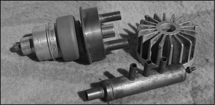
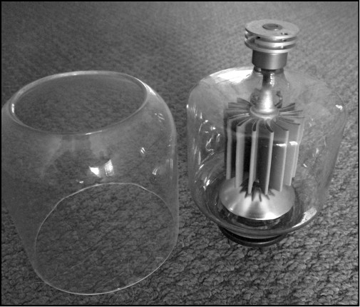
GI-7BT Russian triode with the liquid cooling adapter and the original air cooled radiator.
Sockets for these valves use a coaxial technique and they really should have finger-stock grid grounding rings. But they can be solidly mounted as long as you take care not to stress the anode portion. The air cooler is easily removed and this leaves a copper stud threaded M6 to which you can attach another cooler type. The copper stud must not be over-tightened as it will strip the threads.
The subject of liquid cooling is covered in Chapter 13.
The filament / heater is rated at 12.6V AC or DC and draws about 2A. It is an indirectly heated cathode, but in common with most microwave triodes the cathode and one end of the heater share the cathode pin. The smallest pin is the other end of the heater and the next larger is the cathode. The largest cylinder is the grid terminal.
For VHF / UHF operation the driving of the cathode is not difficult with the correct matching network. The details of the 6m amplifier I built are contained in RF Design Basics [1], which covers all the necessary constructional facts. There are also microwave amplifier designs I wrote for Microwave Projects 2 [2], with additional cooling methods.
Having sung the praises of the 3-500Z, I feel it necessary to warn you these are not cheap valves! The most recent price I was able to find was nodding around the $200 mark for a new Chinese version, and some of these have a chequered reputation. But I am also aware of at least two amplifiers that have the original Eimac 3-500Zs in them with over 30 years on the clock without a valve replacement. They are a little bit down in power, but far from being extinct.
references
[1] RF Design Basics, by John Fielding, ZS5JF, published by RSGB, 2007.
[2] Microwave Projects 2, edited by Andy Barter, G8ATD, published by RSGB, 2003.

