9: Grounded Cathode Linear Amplifiers
The most common type of RF amplifier, before the grounded grid amplifier
became fashionable, was the grounded cathode stage. This is also commonly known as the grid driven amplifier. This type of amplifier is generally reserved for tetrode and pentode valves as they have much lower anode-grid feedback capacitance. Hence, they can sometimes be used without any neutralising. One advantage of the grid driven amplifier is the low power needed to drive them. Often as little as 1 watt is adequate to drive a pair of valves to full output of about 100W PEP. Hence, this type of amplifier has high gain and suited the 100W class of SSB transmitter well. Many HF transmitters used commonly available colour television valves, as they were freely available and cheap.
One popular valve was the American 6JS6C and many Japanese valve manufacturers, as well as US companies, made them in large numbers. These gained the name sweep tubes as in colour television service they were used to deflect or ‘sweep’ the spot of light across the phosphor screen. However, they are not designed as truly linear valves and they have certain limitations.
To solve some of these problems RCA stepped in and did some work on their sweep tubes and brought a new valve on to the market, the 6146. This was in early 1952. In its original form it was a glorified sweep tube with some characteristics altered to suit RF amplifier service. There is also the 6159, which is a true sweep tube, and altered from an earlier design. The 6146 in the original advert didn’t specify operation using SSB; instead it was targeted at the VHF mobile radio market using AM and FM.
Only later did RCA begin specifying the SSB operational needs, as the new mode gained traction with users. The valve went through numerous improvements, each one a small tweak to its internal construction, but only later brought out the first major revision, the 6146A, in mid-1963. This did now mention linear operation for SSB in Class AB1. RCA had patented a new cathode structure, which they dubbed ‘dark heater’ as it didn’t glow as brightly as the earlier types and required a little less heater current. They state in the data sheet for the 6146A that “The 6146A is unilaterally inter-changeable with the 6146”.
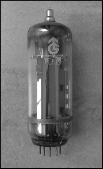
The PL519, a TV ‘sweep tube’ type valve.
Later still the 6146B appeared, in early 1964, which was virtually the same valve but with a few extra changes to improve the performance. It was also given a double part number of 6146B / 8298A. In the data sheet it stated that the “6146B is unilaterally inter-changeable with the 6146, 6146A and the 8298”. The exact date the 8298 was introduced is hard to determine, but it must have been sometime after the 6146A appeared.
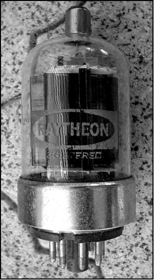
The 6146B pentode, originally manufactured by RCA.
The military liked the new valves but needed a more rugged version to withstand high shock and vibration. This appeared as the 6146W in 1963 also with a double part number of 7212, which used the 6146A internals and not the later 6146B. Apart from the more rugged internal bits all the 6146 valves are, to all intents and purposes, identical in use: the 6146W is not a higher power version of the normal 6146 as some people have been led to believe. If the RCA data sheets are studied for all the variants it can be seen that it has identical parameters to the other types. They all have identical gm values of 7mA/V, so the W version does not draw any more current, or put out any greater power, than the others for the same operating conditions.
Along with the 6146 series another series gained popularity with the two-way radio market. This was identical apart from the heater voltage being 12.6V instead of the 6.3V of the 6146. This was made by several US valve manufacturers and is the 6883B / 8032A. In every respect they are 6146 valves but with 12.6V heaters. Again the confusion in the A and B type numbers show they are modified from another series!
Both the 6JS6C and the 6146 series are very similar and can safely handle up to 850V on the anode. Mullard also manufactured the 6146 under licence as the QV06-20. This part number at least tells us something about the valve. The Q means it is a RF beam tetrode, the V denotes an oxide-coated indirectly heated cathode and 06 is the maximum anode supply voltage in kV, hence 600V. The final number gives the anode dissipation in watts.
The 6JS6C in the General Electric data sheet states it is a beam pentode, but all other manufacturers class it as a beam tetrode. It has similar anode voltage rating (990V), but in sweep tube duty the fly-back voltage can reach several kV; it is rated at 7.5kV peak. The anode dissipation is higher than the 6146 at 30W. However, being a true sweep tube, the RF performance is slightly inferior to the 6146 series. It has a higher gm value than the 6146 of 11.5mA/V, so it draws more current for the same drive level and as such has more gain.
The 6146 series has the 8-pin octal base while the 6JS6C has a 12-pin base. Both valves have the anode top-cap fitting.
A question often asked is “Which of the two is the better valve?” That depends on what you mean by better. If it is the anode dissipation, the 6JS6C is clearly better on paper. However, the ICAS rating of the 6146 is upped to 25W, so there is little difference. If you mean performance, really there is little to choose between them at HF. The 6146 will work up to 145MHz at reduced ratings, the 6JS6C pretty much is dead past about 40MHz. If you mean availability and cost, the 6146 series seems to have the edge; colour televisions haven’t used valves for a long time. Consequently, hardly any valve manufacturers are making them today.
Higher Power Valves
When more power is needed several valves are available that can satisfy the requirement. Of course, the gain is probably going to be a little lower but the drive power needed is not excessive. Many tetrodes with an anode dissipation of 200W to 400W are still available and offer a good deal more power than a pair of 6146s.
The Eimac 4-250 and the 4-400 are still available if you look hard enough and are real workhorses for big HF linear amplifiers. They also go under different part numbers by other manufacturers. These are traditional glass envelope valves and quite large. An alternative is the compact metal-glass or metal-ceramic forced air-cooled versions, such as the Eimac 4X150 and later series of the 4X250, 4CX250 and 4CX350. These will work all the way up to 432MHz, except the 4CX350 which doesn’t really work well even on 144MHz, as it falls over above 120MHz. For HF amplifiers a single 4CX350 will give plenty of power and only needs a sniff of drive to make them work.
One of the older valves is the RCA 813. This valve was first introduced in 1938, just in time for the outbreak of war, and during the war they were made in vast quantities, mostly by Westinghouse in Canada. After the war they quickly became the valve of choice for AM transmitters running the then 1kW DC input limit in the USA. The war surplus sales saw huge quantities dumped on the open market at bargain basement prices. The anode is a graphite construction and they can stand a fair amount of abuse, but the official anode dissipation is only 100W in CCS ratings and 125W under the ICAS rating. As such they are lower power than the later 572B but being a high gain valve required very little drive to make them work. At 30MHz as little as 5W drive was adequate for a Class C AM / CW transmitter.
Like most high power transmitting valves they are a high voltage-low current valve. Many amateurs in the UK used them, but due to the licence limitation of only 150W DC input for AM and CW they used an abnormally low anode voltage. When SSB operation became popular the use of the lower anode supply seemed to persist. The 813 really only starts to wake up above 1500V and 2.5kV is even better. Under 100% modulation AM duty they withstand 4kV on the anode during speech peaks although RCA recommends the anode supply should not exceed 2kV under this service. In practice, they still won’t flash them over with 5kV or even a little more. As with most beam tetrodes, the screen grid voltage selection and regulation is critical for optimum linearity. For maximum output they require 750V on the screen grid. In order to get around the bulky screen grid regulated supply, several amateurs began experimenting with alternative methods. The first was G2MA who published a design using a single 813, but it had a few problems. The problems were tackled by another amateur.
This was Richard (Dick) Thornley, G2DAF, whose callsign has become famous (or infamous, depending on your point of view) for his radical new method of supplying the screen grid. Unfortunately, many amateurs failed to read and digest what G2DAF was trying to put across and they did not follow his instructions to the letter. Consequently, the G2DAF linear earned a bad name. This was unfair, because what G2DAF pioneered has become the basis of super-linear amplification methods in more recent years.
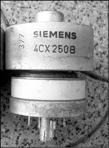
The Siemens 4CX250B.
G2DAF linear amplifier
The G2DAF design does not require a grid bias supply or a normal screen grid supply, yet provides a very linear signal – if correctly constructed and set up. Many
of the modifications made by others to the original design only served to convert it into a ‘splatter-box’ amplifier. This was due to a misunderstanding of the design concept.
The concept is to use a normal tetrode in a zero bias condition with the input signal fed into the normal grid. The subtle difference is that the screen grid voltage is not supplied with a constant DC voltage. It is supplied with a half sine wave DC signal obtained by rectifying the input signal. Consequently, when no drive is applied the screen grid and control grid are both at zero volts and the valve is virtually cut off. When an input signal is applied, the screen grid rectifier supplies a DC voltage which accurately follows the input grid voltage. This means that when the valve is driven to maximum grid input the screen grid voltage rises to a peak. It is a type of efficiency modulation method now widely used in the RF industry to provide very linear amplification.
The G2DAF amplifier is quite different to a normal amplifier using a beam tetrode. In a normal linear, to ensure good linearity, the idle anode current needs to be fairly high; this dissipates a lot of power. The G2DAF feels more like a Class C type of amplifier and, the first time you experience it, it takes a while to get used to the behaviour of the anode current meter. Because the valve does not dissipate any power when not driven the anode temperature is a lot lower and it can be talked up a lot higher on peaks than a normal amplifier. The efficiency is high and the power output is also higher than a normal amplifier using the same valve. In fact, a single 813 running on a 2.5kV anode supply will easily develop more than 400W PEP with good linearity at HF in a good circuit.
However, the screen rectifying system and the reservoir capacitor are critical items to make the amplifier work correctly. Most of the modifications use a reservoir capacitor that is far too large. This slows down the rise in screen voltage and also holds it up for too long after the peak has dropped away.
G2DAF did not originally use the 813, he used other valves to prove the concept and only later the 813 became the valve of choice because they were so inexpensive and available in huge volumes. G2DAF later gave some experimental data on an amplifier using 4X150 valves and these also work very well. Practically any suitable beam tetrode will work, though some are better than others, and will give ample power with good linearity – but only if you follow the circuitry as G2DAF described it.
The screen supply rectifier can be a source of trouble if an unfavourable diode is selected. The best type is a valve rectifier. Although today we have many semiconductor rectifiers able to handle the high voltages required, not all work as well as the old fashioned valve types.
The original article appeared in the R.S.G.B. Bulletin in April 1963 and it is imperative that this article be studied before attempting to build a G2DAF linear. Although follow-up articles appeared later they did not have all the vital information contained in the first article.
An improved screen rectifier was also shown which gave better screen supply characteristics. This uses the Cockcroft-Walton voltage doubler circuit, requiring less input drive to work adequately. (John Cockroft and Ernest Walton were two Cambridge University scientists who split the atom in 1932. They devised a particle accelerator to shoot protons, the nuclei of hydrogen atoms, at a target of lithium metal. In order to accelerate the protons they needed a very high DC voltage generator, and so the Cockroft-Walton voltage multiplier came about.) The basic concept, from the April 1963 RSGB magazine article, is shown in Fig 9.1 and the improved screen supply schematic is given in Fig 9.2.
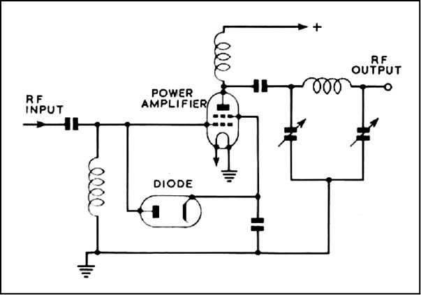
Fig 9.1: Original G2DAF concept schematic.
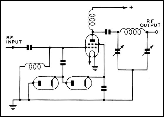
Fig 9.2: Improved screen supply schematic.
The critical item is the reservoir capacitor shown decoupling the screen grid pin of the RF amplifier stage. This must be large enough to completely decouple the screen grid to RF signals, but not so large as to slow down the audio waveform from the screen rectifier. To demonstrate the typical performance G2DAF gave the graph shown in Fig 9.3 when using two QY3-125 beam tetrodes, as used in the original experimental amplifier.
If you care to plot out the valve characteristic versus input drive level you will discover that the method gives almost a perfect Class A slope. This is because the screen supply is always such as to give an available anode current to place the point of operation in the middle of the Class A slope, but only if the screen grid rectifier is correctly proportioned. This is why the IMD performance is so good, it is as if the amplifier is running true Class A, but without the poor efficiency that Class A normally gives.
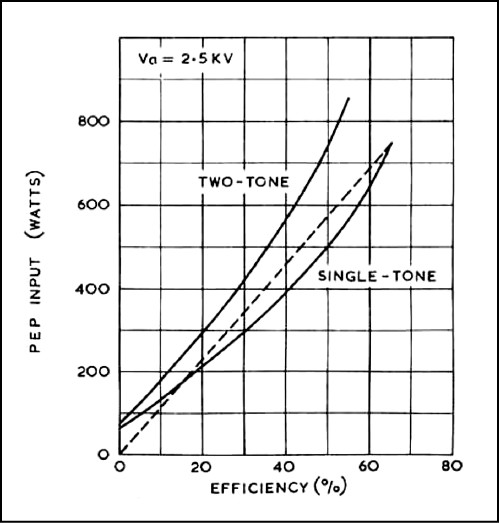
Fig 9.3: Measured performance of the G2DAF linear.
From this graph the improvement of the G2DAF amplifier versus a conventional Class B type is clearly evident. The amplifier is better under two-tone operation as more input power can be achieved for the same input drive power. G2DAF did not give any IMD measurements, because he did not have access to the necessary test equipment. Later versions have been measured and they give acceptable results compared with grounded grid triode amplifiers. Typically, the third order products are about the same but the fifth order and higher are better.
The original schematic of the G2DAF linear is given in Fig 9.4.
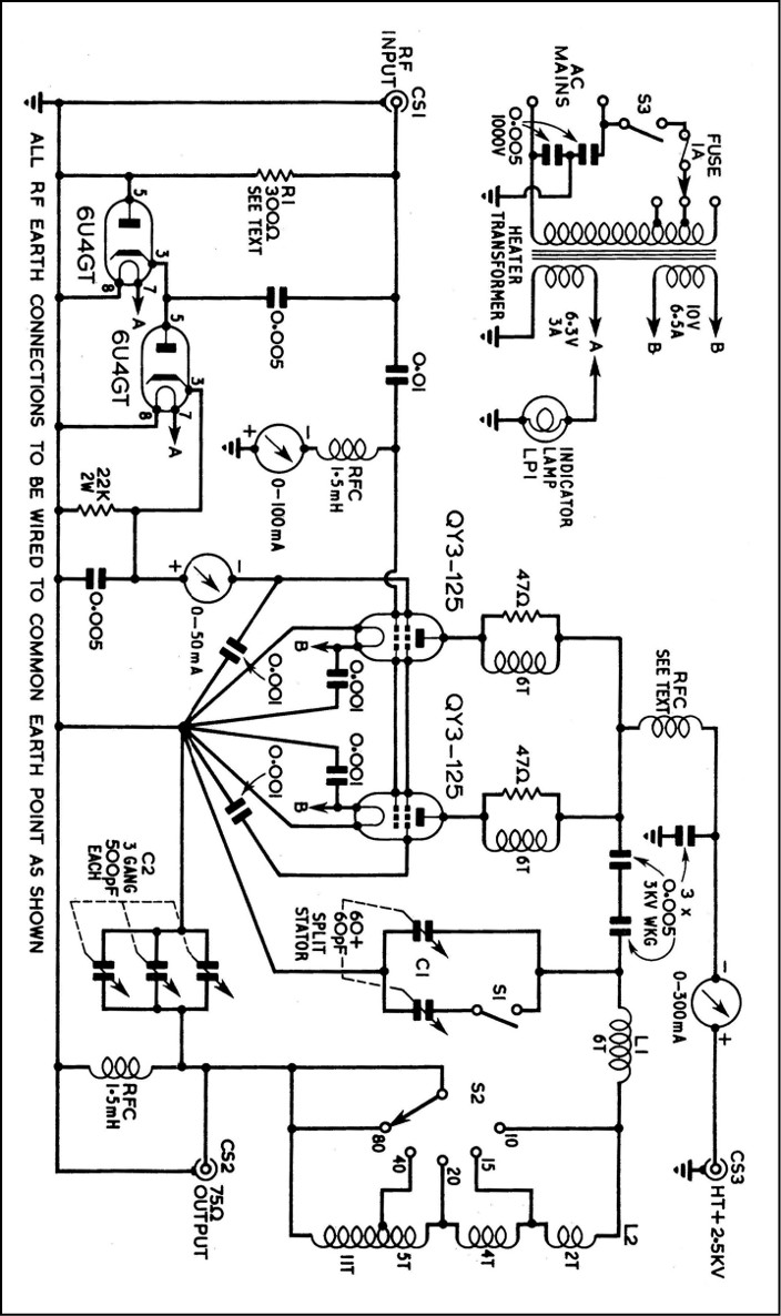
Fig 9.4: Original G2DAF amplifier schematic.
The important parts are the way the screen grid rectified voltage is filtered, and this is where the majority of the alleged problems with the G2DAF amplifier arise. Many constructors misunderstand the way the screen grid voltage should behave. Consequently they use unsuitable values and then the amplifier generates splatter, because the supply is not working correctly. The earlier G2MA amplifier uses a similar approach but Dick Thornley made the breakthrough in eliminating the screen supply using conventional methods.
The time constant of the smoothing is critical to get the correct waveform. In
Fig 9.4 the output of the second diode rectifier has a 22kΩ resistor to ground to form a bleeder path to discharge the smoothing capacitors. The smoothing capacitors consist of three decoupling capacitors connected to ground. Each valve screen grid has a 1nF capacitor plus the rectifier has another 5nF capacitor, making a total of 7nF. The 22kΩ resistor with these caps forms a time constant which allows the DC voltage to correctly follow the instantaneous RF input waveform, just like an AM detector stage, which is what it is. If the resistor has too high a value, or if the capacitors are too high, the DC voltage will not follow the input waveform faithfully. The values shown give a cut off frequency of about 6.5kHz, which is about twice the normal speech signal maximum. If this time constant is too long the DC voltage will hold the peak voltage up for too long a period, or fail to rise quickly enough, and splatter will occur.
An Alternative Modern Version of the G2DAF Linear
One improvement that can be made is to adopt the passive grid resistor method instead of an input tuned circuit. Using this method the driving power needs to be greater and this also gives better linearity of the screen rectifier scheme. G2DAF mentioned this when the high perveance 4X150 valve was tested. He used a tapped input resistor to obtain a greater rectifier voltage and a lower grid driving voltage. Today a possible scheme would be a wide-band ferrite transmission line transformer (Ruthroff type) and a 2:1 step-up in driving voltage for the screen grid supply. A possible circuit is shown in Fig 9.5. V1 can be any of the popular valves.
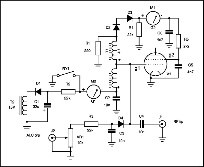
Fig 9.5: G2DAF alternative modern version.
The drive input is applied directly to the grid via a blocking capacitor. A wide band ferrite 4:1 impedance transformer (T1) transforms the 50Ω at the input up to ~200Ω and hence at this point the RF voltage is twice the grid voltage. The half wave rectifier consisting of D2, D3 in series (to obtain sufficient PIV for the diodes used) feeds the screen grid supply. These diodes need to be fast diodes, preferably Schottky types. Meter M1 measures the screen grid current. R4, R5 and C5, C6 provide the screen grid voltage time constant.
The 220Ω resistor (R1) at the output of the 4:1 transformer terminates the transformer and also reflects back through the transformer to give a ~50Ω match to the driving source. This resistor needs to be rated for the full drive power and it must be a low inductance type. It can be made up of several higher value resistors in parallel to suit the power level required. Transformer T1 should be wound on a powdered-iron toroidal core to suit the frequency of operation. An Mn-Zn high frequency type, such as a 4C65 mix, would be appropriate.
During receive periods a small transformer (T2) supplies a negative cut-off bias to the grid of V1 to ensure it does not generate noise. Relay contact RY1 is open on receive and shorted on transmit. The grid current meter (M2) then displays the grid current. Diode D4 supplies the ALC signal to the driving source to ensure the stage is not over-driven.
Other efficiency modulation methods
The G2DAF amplifier sparked other experimenters to undertake further investigation on this type of amplifier. Some difficulty was experienced in getting the correct ratio of input drive to screen grid voltage to suit different valves. One solution was to use a slightly different method. This used a series regulator valve to supply the screen grid from a DC supply, as in the original G2MA design. This was a modification of the series gate or clamp valve system used for Class C amplifiers for CW.
In this method the input drive is rectified and used to provide a negative DC voltage. A clamp valve using a beam tetrode, often strapped as high power triode, is used to hold the screen grid to a low voltage via a dropper resistor fed from the normal anode supply or a lower supply rail. Under key-up conditions the screen voltage is clamped to a low level, such that the output valve draws very little anode current. When the key is down and full carrier applied to the grid, the negative rectified voltage now biases off the clamp valve and the screen voltage rises to the normal voltage. The basic circuit is shown in Fig 9.6.
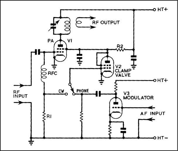
Fig 9.6: Clamp valve circuit.
The clamp valve schematic shown has two extra valves apart from the normal RF amplifier valve V1. V2 is the clamp valve and it is supplied with anode current from the main anode supply for V1. Resistor R2 sets the screen grid voltage on V1 when the clamp valve is not holding the voltage down. The grid-1 of V2 is either connected to the grid voltage of V1 when the switch is in the CW position or to the output of a second valve V2, which supplies an AC signal provided by the speech amplifier circuitry, when the switch is in the Phone position. By switching to the Phone position, the clamp valve function is disabled and audio is fed to the screen grid so swinging it about the nominal bias point. This serves to form a simple AM modulator. (In later years this became known as series gate modulation. Today it is the main method used for eliminating non-linearity in solid-state power amplifiers when the complex input signal is varying in amplitude.)
It doesn’t take much to convert this type of circuit to a way of swinging the screen grid voltage upwards when the input signal is rising in level. The grid signal of V1 is rectified and the diode provides a negative voltage to bias off V2, as per the original. V3 could be dispensed with or used to assist with the voltage regulation of the screen grid supply. In later adaptations V2 was changed to a series regulator valve and driven with a positive rectified voltage. By scaling the regulated output voltage of either the rectifier or the screen regulator the linearity could be optimised. The writer used this method for several years to control a QQV06-40 for 2m SSB and it gave excellent results. The rectified input voltage serves as the reference voltage of a high voltage series regulated supply. The output voltage is sampled and as the reference voltage varies the output voltages follows it with virtually zero error or lag.
Today there are many suitable high voltage MOSFET devices that would suit the application in a type of variable shunt regulator screen supply. The whole control system could be solid-state and adjusted under test to find the correct ratio of screen voltage to input drive level. All that is required is a linear AM detector circuit to sample the input drive signal and an op-amp for DC control of the MOSFET gate drive. The writer used such a circuit for a low power transmitter using a 6146 valve to generate very linear AM modulation for an 80m test amplifier to evaluate IMD performance in HF amplifiers.

