Chapter 5 -
Replacing a Broken Power Supply
In the unfortunate (and surprisingly common) event that an Xbox breaks after its three month warranty period expires, the only official way to fix it is to pay Microsoft for the repair bill. Even the simplest fixes can cost over one hundred dollars, or about half the original purchase price of the console. As a result, I have received numerous emails from people asking how to fix broken power supplies and hard drives.
Unfortunately, replacing a broken hard drive requires defeating the Xbox security system, since a unique key is used to lock Xbox motherboards to a particular hard drive. Installing a new hard drive would require a modchip that can reprogram or bypass the hard drive lock. Furthermore, a copy of the factory-installed Xbox software is required, something that is illegal to distribute or copy even for repair purposes. Therefore, the topic of Xbox hard drive replacement is too dicey to be discussed in this text. Readers are encouraged to search online for any of the numerous FAQs about replacing hard drives.
On the other hand, the power supply used in the Xbox is very similar to that used in a standard PC. There are many websites where you can purchase exact replacement Xbox power supplies, such as Llama.com (www.llama.com/xbox/Repairs/repairs.htm), XboxRepair.com (www.xboxrepair.com), and Firefly-HK (www.firefly-hk.com), or you can attempt to build one yourself out of a standard PC power supply!
Considering the frequency of power supply failures, I will show you how to adapt a standard PC ATX power supply for the Xbox. The approach described in this section requires no soldering, at the expense of having to flip an extra switch to power on the Xbox. Appendix C, “Getting Into PCB Layout,” describes a simple project that you can build to have the convenience of no additional power switches. Of course, it is easier to purchase an exact replacement power supply for the Xbox and use parts of the procedure presented in this chapter to help you with the installation. However, there is less educational value in doing a direct replacement than in doing an adaptation. If you decide to adapt the ATX power supply for use with the Xbox, you will learn how to make crimp cables as well as learn a little bit about electronics theory and how the Xbox works.
Another reason for adapting a standard PC ATX power supply to the Xbox is to provide extra power to the console. The OEM (original equipment manufacturer) or “stock” Xbox power supply puts out just barely enough power to meet the Xbox’s demands. Connecting extra drives or fans to an otherwise unmodified Xbox can overload the OEM Xbox power supply and cause it to burn out.
Note that as of this writing, a new hardware revision of the Xbox (known as “v1.2” in the Xbox hacking community) was released that appears to have a standard ATX power supply connector, instead of the proprietary Xbox power supply connector described later in this chapter. Check to make sure that your Xbox power supply connector matches the connector described in this chapter before proceeding with the adaptation procedure. The Xbox power supply connector assumed in this chapter has twelve pins in a single row, whereas the newer Xbox power supply connector has 20 pins arranged in two rows of ten. Also, even though the latest Xbox hardware revision has an ATX-like connector, it is not necessarily electrically compatible with a standard ATX power supply. It would be prudent to measure the voltages on the power connector and compare them to the ATX specification (www.formfactors.org/developer/specs/atx/atx2_1.pdf) before attempting to mate a standard ATX power supply to an Xbox with the new ATX-like connector.
Caution

Replacing a power supply may expose you to hazardous voltages. Before removing the power supply, always unplug the Xbox from the wall outlet and wait a minute for stored charges to dissipate. In addition, improper installation of the replacement power supply could result in permanent, even explosive, damage to the console. Only perform this procedure if you are sure that the power supply is discharged and off, and if you are willing to take the risk of further damaging your console.
Diagnosing a Broken Power Supply
If your Xbox is experiencing problems powering up, you must first diagnose the problem and locate the source of failure. It does no good to replace a power supply when the fault is actually within the console or in the wall outlet. Perform these diagnostic steps to verify that the Xbox power supply is in fact the culprit, and not something else.
- Verify that the power outlet is functional by plugging a lamp into it. Use a 100 watt lamp minimum to accurately simulate the load of the Xbox.
- Visually inspect the power cord for kinks and cuts.
- Verify that the power cord plug is firmly seated in the Xbox power receptacle, and that the Xbox still does not turn on despite these checks.
- Visually inspect the inside of the Xbox for char marks or ruptured capacitors. If char marks are visible on the motherboard, you may have to replace the Xbox motherboard (i.e., buy a new Xbox). If there are char marks on the power supply, most likely the power supply was damaged and you may begin replacing it. (Keep in mind that a power supply failure may also damage the motherboard, so there is still a chance that the Xbox will not work once the power supply is replaced.)
- Verify that the main power supply connector and the front panel circuit assembly connector are firmly seated. (The location of the front panel circuit assembly connector is illustrated in Figure 3-3 of Chapter 3, “Installing a Blue LED.”) The power switch for the Xbox is connected to the motherboard through the front panel circuit assembly connector.
- While the Xbox is off but stil plugged, use a voltmeter to verify that the 3.3V standby voltage (3.3VSB) is within specification. Measure 3.3VSB by probing the sixth wire in the power supply connector from the end closest to the front panel, and any of the black wires on the power connector. You can measure power supply voltages by inserting the tips of a voltmeter probe into the free space between the power wires and the power connector. (There is a metal collar around the power wires inside the motherboard power connector’s body.) If the value of 3.3VSB is not between 3.14 to 3.47 volts, you may need to replace the power supply.
- Press the power button on the Xbox to turn it “on” (presumably, if the power supply is broken the Xbox won’t do much). If the power supply makes noise or smokes, unplug the box and proceed with replacing the power supply. If the box seems dead, measure each of the primary voltages coming from the power supply. The yellow wire should have a voltage between 11.4 to 12.6 volts; the red wire should have between 4.8 to 5.25 volts; and the orange wire should have between 3.14 to 3.47 volts. (All of these voltages are referenced with respect to the black wire.) Also, check that the voltage on the Power OK signal (located at pin 12, the pin farthest from the front panel) is above 3.1 volts.
If everything in the list on the previous page checks out, it is quite unlikely that the problem is with your power supply. Further things to check are the electrical and mechanical integrity of the power switch (see Chapter 3 for how to remove the board with the power switch) and the functionality of the motherboard. However, if you did observe indications of a failed power supply, read on.
Replacing the Power Supply
The overall strategy for replacing the Xbox power supply is to adapt a standard PC ATX power supply for use in the Xbox. Here is a list of the equipment you will need:
• A standard ATX power supply. A 1-U power supply will fit within the footprint of the Xbox case, but it will probably be a little bit too tall to close the case.
• (Optional) An ATX motherboard power cable extension. Power cable extensions can be purchased through numerous vendors, including PC Power and Cooling www.pcpowerandcooling.com). Modifying the extension cable for the Xbox instead of the ATX power supply’s cable allows you to reuse the power supply in a standard PC once you are ready to toss your Xbox.
• A crimping tool. The Molex universal crimping tool (Digi-Key part number WM9999-ND) is highly recommended, but it is a little bit expensive (about $35). A cheaper crimping tool, such as the Jameco 159265, can be purchased for about a third the price but it is more frustrating to use and you may have to use solder on the crimps to achieve the desired connection strength.
• One 12 position 0.156" pitch connector housing (i.e. Digi-Key part number WM2313-ND)or two stacking 6 position 0.156" pitch connector housings (i.e. Jameco part number 104731). This housing is used for the Xbox power connector replacement.
• Thirteen crimp terminals for the 0.156" pitch power connector (i.e. Digi-Key part number WM2313-ND or Jameco part number 78318).
• Two 1N4001 or better silicon rectifier diodes in a DO-41 package (i.e. Digi-Key part number 1N4001DICT-ND or Jameco part number 35975).
• A wire stripper. Any wire stripper that can handle 18 gauge wire will do.
• A wire cutter. Any diagonal wire cutter will do.
• Electrical tape.
Using Diodes to Drop Voltages
The Xbox requires a +3.3V standby supply voltage, but an ATX power supply only outputs a +5V standby supply voltage. The “correct” solution to this problem would be to use a voltage regulator that precisely converts +5V into +3.3V, but the goal of this hack is to replace the power supply with a minimal amount of soldering.
The alternate solution is to use two diodes to reduce a +5 volt supply down to a “close enough” +3.6 volt supply. We can do this because the voltage across a forward conducting diode is logarithmically proportional to the current through the diode. In other words, for most currents, the voltage across a diode is almost constant. It turns out that silicon diodes almost uniformly have a forward voltage drop of about 0.7 volts, so two of them in series will drop 1.4 volts.
The diodes used in this hack, the 1N4001, are only capable of conducting 1 ampere of current, so don’t use this trick in other applications that require a large amount of current. Fortunately, the stand-by supply for the Xbox only needs to draw a tiny amount of current so burning out the diodes is not a concern.
As a final note, the voltage dropped by a diode fluctuates slightly with the amount of current through it, so do not use this trick in applications that require precisely regulated voltages. In the Xbox application, we are running the voltage a little bit on the high side, but fortunately the digital logic powered off of this supply can tolerate this condition.
Strategy
The interface for a standard ATX power supply is very similar to that of an Xbox’s power supply. The Xbox requires +3.3V, +5V, +12V, a +3.3V standby supply, as well as two control signals, “power OK” and “power on.” The power OK signal indicates that the power output from the power supply is stable and properly regulated, and the Power On signal is a control signal from the Xbox that turns the power supply on and off. A typical ATX supply has +3.3V, +5V, and +12V outputs with enough juice to run an Xbox, and it also has a power OK signal that is compatible with the Xbox motherboard. However, an ATX power supply generates a +5V standby voltage instead of a +3.3V standby voltage, and the Power On signal has an inverted polarity from the Xbox. Both of these incompatibilities can be addressed in a manner that requires no soldering. Two diodes in series are used to reduce the +5V standby voltage down to a voltage of a little less than +3.6V. The Power On signal to the ATX power supply defaults to “on,” so it will remain unconnected, making the power supply always on even if the console is off. This isn’t problematic for the console’s electronics, but it might be aesthetically disconcerting. Appendix C, “Getting Into PCB Layout,” describes a sample design that you can implement to avoid these incompatibilities in a more graceful manner. However, the design outlined in the appendix will require you to invest some effort in the form of soldering and board design.
Procedure
The procedure for replacing the Xbox power supply consists of two parts:
- Modifying the standard ATX power cable to be an Xbox power cable.
- Removing the old power supply and installing the new one.
Building the Xbox Power Cable
Begin by cutting off the existing ATX power supply’s motherboard connector as shown in Figure 5-1. You may elect to perform this modification using an ATX motherboard power extension cable, so you can preserve the ATX power connector on the power supply for future use. The procedure is identical for both options, but the pictures in this chapter are taken using the ATX motherboard extension cable.
Now, attach crimp terminals to the following wires ten of the ATX cable, as shown in Figure 5-2:
• One yellow wire
• Three red wires
• One orange wire
• Four black wires
• One gray wire
If you are using a cheaper crimp tool, you may have trouble making a sufficiently strong crimp connection. In this case finish the connection by soldering the crimp terminal onto the wire. Use a copious amount of heat when soldering, or else the solder will not fully penetrate the wire and the crimp terminal. The soldering iron should be in contact with the joint for about five seconds before and after applying the solder.
On the violet wire (the +5V standby wire), attach two diodes in series between the end of the wire and the crimp terminal. The procedure shown in Figure 5-3 uses portions of crimp terminals for connecting the diodes, so no soldering is required. (Note that diodes are polarized devices: they will not conduct electricity if they are installed backwards. The diodes should be installed with their cathodes (the end with the band painted on it) toward the motherboard.)
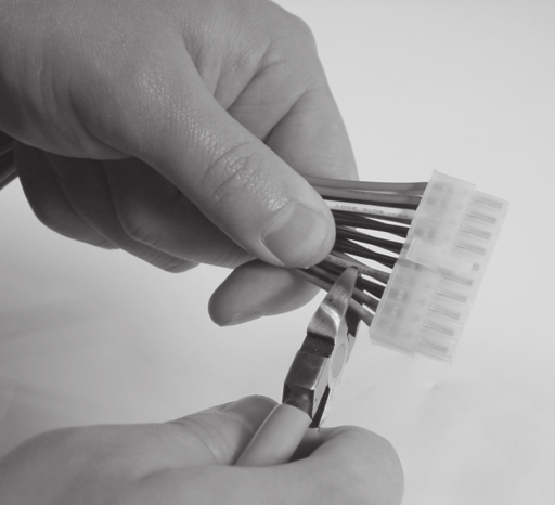
Figure 5-1: Cut the connector off of the ATX power supply cable.
Next, wrap all of the unused wires on the ATX cable with electrical tape to prevent any accidental shorts that will damage the power supply and possibly the Xbox. Be sure to also wrap the diodes with electrical tape as well . (See Figure 5-4.)
Finally, insert the finished crimp terminals into the 0.156" connector housing. The crimp terminals will lock into place inside the housing when they are fully and properly inserted. (See Figure 5-5.) Insert the wires in the order specified in Table 5-1.
Some vendors do not sell the larger 12 position connector housing. In this case, use two six position connector housings, and pay special attention to the ordering you choose for stacking the connectors. Also, note the location of pin 1 with respect to the polarizing lip of the connector. Pin 1 is located at the top of the connector when the polarizing lip is on the left and you are viewing the connector from the side from which the wires are inserted (the top view). Since it is very easy to invert the connector and reverse this in some way, use the existing Xbox connector as a reference. The yellow, red, orange, and black wires should all line up when compared with each other.
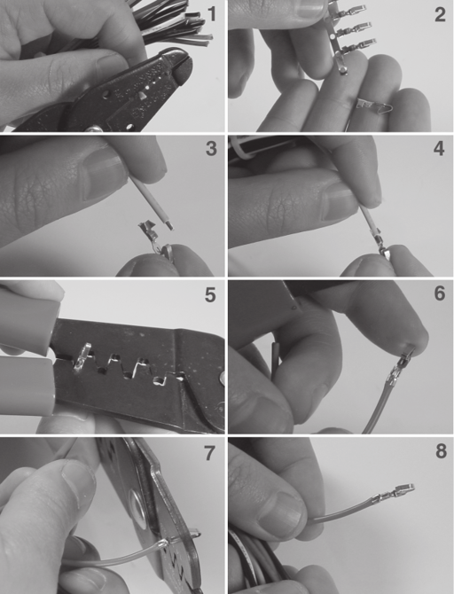
Figure 5-2: Attaching a crimp terminal to the end of a wire. (1) Strip about 1/8" of insulation off the end of the wire. (2) Remove a virgin crimp terminal from the retaining strip, if necessary. (3 and 4) Insert the wire into the crimp terminal, such that 1/16” of insulation is sitting between the longer pair of crimp fingers. (5) Crimp the insulation portion (longer pair) of the crimp fingers. (6) Shows the wire with just the insulation portion crimped. (7) Crimp the conductor portion of the crimp fingers. (8) The finished crimp terminal. The conductor crimp terminals should be folded in tightly on the bare wire for good contact. Test the crimp connection by firmly pulling on the terminal end.
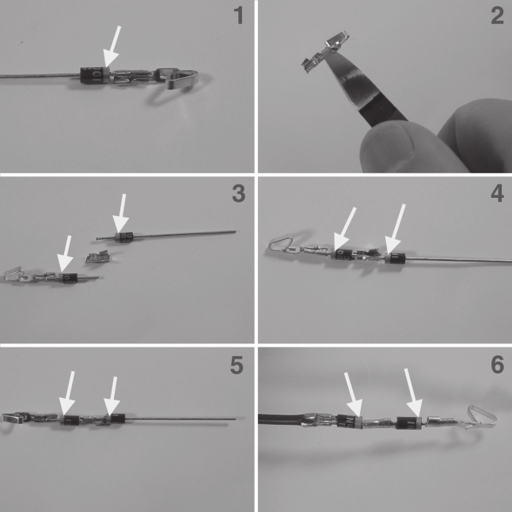
Figure 5-3: Attach two diodes in series between the end of the violet wire and the crimp terminal that goes into the power connector. Arrows indicate the proper orientation of the polarizing line painted on the end of the diode. This procedure will consume a total of three crimp terminals. (1) Attach one diode to a crimp terminal with the polarizing band near the crimp terminal. (2) Cut a crimp terminal in half to remove the leaf contact. (3 and 4) Position the diodes within the crimp portion of the severed connector, noting the polarity of the diodes. (5) Diodes shown after crimping. (6) Attach the diodes to the end of the violet wire using the same procedure with a second severed crimp terminal.
Double check your work after completing the assembly of the power supply cable, as any error could result in permanent, irreparable damage to the console. Figure 5-6 shows what the finished connector assembly should look like. You may wish to use a cable tie, if available, to bundle the unused wires so that they do not get in the way and accidentally short or become damaged.

Figure 5-4: Wrap the unused wires and diodes in electrical tape to prevent accidental shorting.
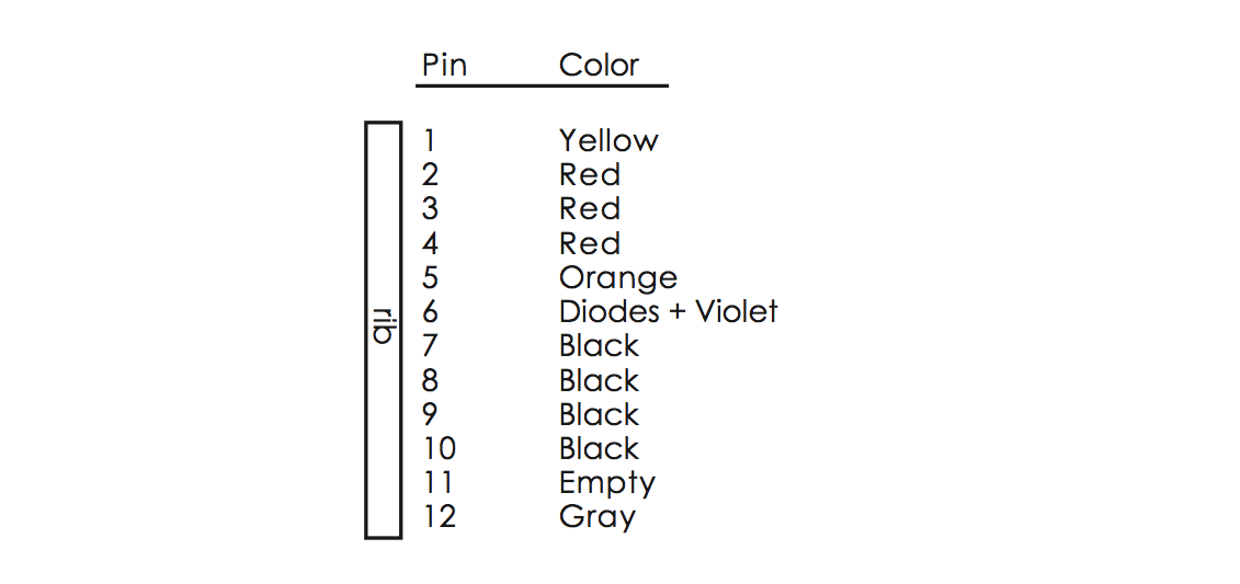
Table 5-1: Wiring table for connecting ATX power supply cable to Xbox power connector (view from wire entry side, with the polarizing rib on the left).
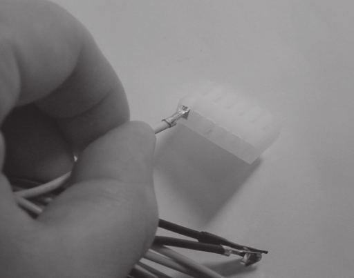
Figure 5-5: Inserting a crimp connector into the connector header.
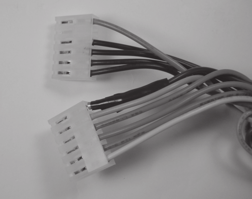
Figure 5-6: The final cable assembly.
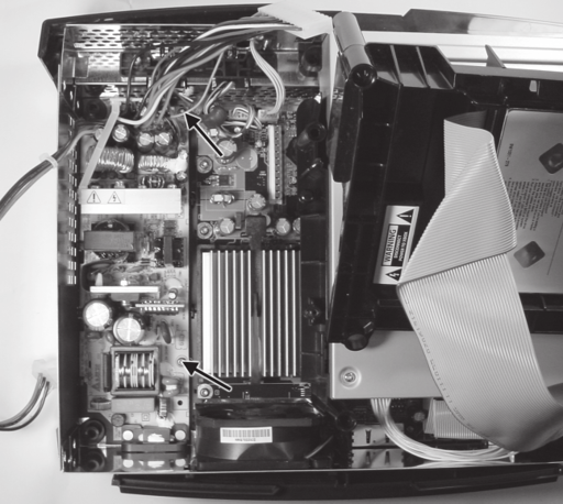
Figure 5-7: Location of the two power supply mounting screws.
Installing the Replacement Power Supply
Now that we’ve prepared a replacement power supply, we must swap out our old, broken one. First, remove the top of the Xbox case as described in Chapter 1, “Voiding the Warranty,” then detach the hard drive power connector and lift the hard drive out of the case. You should not need to detach the gray IDE ribbon cable connected to the hard drive.
Note

At this point, verify that the Xbox is unplugged and that it has had an opportunity to sit for at least a minute to dissipate any stored charge in the power supply. Working on the Xbox while plugged in, or soon after it has been unplugged, is extremely hazardous. The Xbox will deliver a nasty, possibly lethal shock if you touch any part of the power supply with your bare hands before it has dissipated its stored charge.
-
Unplug the Xbox power supply connector by grasping the full bundle of power wires and pulling firmly on the cable while holding the box down with the other hand. Mind the sharp metal edges of the case and heat sinks when removing the cable.
-
Remove the two T-10 torx screws that hold the Xbox power supply in place. (See Figure 5-7.)
-
Lift the power supply out of the Xbox case by first raising the end of the power supply closer to the front of the Xbox.
-
Compare the cable you created with the Xbox power supply cable, making sure to align the polarizing ribs. The red, yellow, orange, and black wires should line up between the two connectors. (This check will help ensure that you do not damage the Xbox through a wiring error on the cable.)
-
Plug your ATX power supply cable assembly into the Xbox power connector. The yellow wire should align with the pin closest to the front of the Xbox. Remember, there is nothing to prevent you from inserting the power cable offset by one or two pins. If you see a bare pin on the power connector, you have inserted the cable by a one pin offset. Double check for this condition because it could permanently damage the Xbox hardware and/or the power supply.
-
Plug the Xbox hard drive into one of the ATX power supply’s disk drive power connectors. The hard drive uses a connector identical to the standard PC disk drive power connector so no modification is necessary.
-
Check to see that no wires are shorted against the case or caught in the blades of the cooling fans. Now, you are ready to power on the Xbox.
Operating with the Replacement Power Supply
Most ATX power supplies come with a power switch on them. Set this switch to off, then plug the ATX power supply in, and then turn the power switch to on. At this point, the ATX power supply will apply power to Xbox, even though the Xbox’s system controller thinks the box is powered off. As a result, the cooling fans inside the Xbox should sping. Now, press the power switch on the front of the Xbox. The Xbox should power on normally at this point. If so, congratulations!
Caution

Some Xbox versions are missing a heatsink fan for the GPU. If your Xbox motherboard does not have a fan mounted directly on one of the chips, then you have such an Xbox. Xboxes that lack a heatsink fan for the GPU are prone to overheating under certain conditions, and must be operated with the disk drives installed over the motherboard for reliable long-term operation. The undersides of the disk drives form an air ducting system that guides air over the GPU heatsink from the main Xbox case fan. (Your ATX power supply cable will prevent the disk drives from installing flush with the case, but this is not a major cause for concern with respect to airflow ducting.)
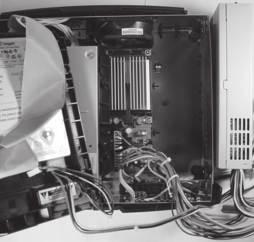
Figure 5-8: 1U slimline ATX power supply connected to the Xbox using the modified ATX power supply extension cable.
When you are ready to turn the Xbox off, you can simply flip the power switch on the ATX power supply. Or, you can use the power switch on the front of the Xbox to power the Xbox off first, and then turn off the ATX power supply.
Debugging Tips
If the Xbox did not power on properly after replacing the power supply, test your power supply cable using the checklist in the section at the beginning of this chapter called “Diagnosing a Broken Power Supply.” The most likely problem you will encounter is a bad crimp connection or poorly or improperly attached diodes. A bad crimp connection may also lead to intermittent operation where the Xbox powers on but crashes frequently.
If the Xbox powers on, but halts during the power on sequence for some reason, see Table 3-1 in the “Debugging” section at the end of Chapter 3 for a list of possible problems and their causes. Appendix E, “Debugging: Hints and Tips,” contains a more in-depth discussion of debugging techniques and methodology.
If the Xbox works properly but crashes occasionally, you may have an Xbox that has no heatsink fan over the GPU. See the Caution note on the facing page describing this problem. To fix this problem, you may need to add an extra fan or enhance the existing ducting system with a piece of paper and some sticky tape.

