Chapter 3 -
Installing a Blue LED
Now that you have taken the cover off of your Xbox, it is time to do a couple of starter projects. The next chapters walk you through some elementary modifications and repairs that you can perform on your Xbox. These projects are designed and written for readers who have little or no experience with hardware hacking. More advanced topics on the Xbox can be found in later chapters.
In this chapter, you will learn how to replace the normally green LED in the Xbox front panel with a blue LED. This project requires minimal soldering; most of the effort is in removing the front panel and the LED circuit assembly. Let’s get started!
Note

A stock Xbox uses a green/red combo LED, but the red LED is only used to indicate error conditions. The procedure described in this chapter will convert your Xbox front panel indicator into a blue-only LED. The proper substitute would be a blue/red combo LED (T-1, 3mm diameter lens). However they are difficult to find, so the instructions here do not use them. The instructions will give the necessary background knowledge for you to improvise and incorporate your own LED solution if you are so inclined.
What You’ll Need
The following is a list of the equipment that you’ll need to complete this project:
• Low-wattage soldering iron with a fine point tip
• Solder
• Flux and soldering iron tip cleaner (optional)
• Smal flathead screwdriver
• T-10 bit Torx driver
• Two low voltage (3 volt) blue LEDs in a T-1 (3 mm) case
• Masking tape for holding parts in place during soldering
You can substitute any color LED that you like, but it must turn on at a voltage of around 3 volts and have a T-1 style case. Pay attention when buying your LEDs, because many blue and white LEDs are rated to work only at 5 volts. The LED used here is a Lumex SSL-LX3044USBC which you can buy through Digi-Key (www.digikey.com); part number 67-1747-ND. (For the budget-conscious, Digi-Key can send the LEDs via United States Postal service’s first class mail. Note that there is a $5 handling fee for orders through Digi-Key that are less than $25.)
If Digi-Key’s minimum order restriction is a problem for you, Mouser Electronics (www.mouser.com) also has a line of blue LEDs, and they have no minimum order. An example part is the Kingbright blue LED in a T-1 case with a water clear lens; the Mouser stock number is 604-L7104PBC/H for the brighter, slightly higher voltage version, or 604-L7104QB/D for a version that operates at a lower voltage but with a lower rated brightness.
You can also use a bi-color LED if you would like to maintain the error condition LED functionality as well. The Xbox requires a common-cathode bi-color LED in a T-1 case with three leads. Unfortunately, bi-color LEDs with a blue element in the smaller T-1 case are very difficult to find.
Removing the Xbox Front Panel
The Xbox front panel is a molded piece of ABS plastic that is held in place with four T-10 torx screws and three molded friction locks. The electronics in the front panel connect to the Xbox motherboard through a single nine-wire connector that winds its way through a hole in the metal electromagnetic interference shield.
Open the Xbox as instructed in Chapter 1. Lift and move the hard drive and the DVD drive up and toward the back of the box just enough to expose the front edge of the Xbox motherboard. You should not have to undo any of the disk drive cables. Figure 3-1 illustrates how your Xbox should look after these steps.
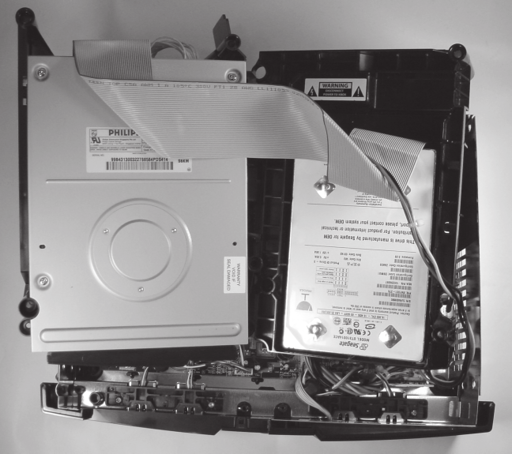
Figure 3-1: Position the disk drives so that the front edge of the motherboard is exposed.
Note

Older Xbox models will have a vertically mounted PC board near the front of the Xbox. This PC board can be removed by grasping the board and pulling it out of its socket. You may find that removing the vertically mounted PC board is helpful when trying to release the middle friction lock of the front panel. Do not forget to replace the PC board when you are done!
Remove the four screws that hold the front panel assembly in place (see Figure 3-2).
Detach the front panel wire connector from the Xbox motherboard as shown in Figure 3-3. A firm, steady force is all the connector should require. (Do not jerk the connector out, because you may damage the wires.)
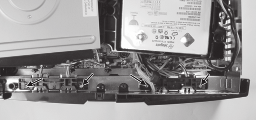
Figure 3-2: Location of the four retaining screws on the front panel assembly.
Now for the tricky part: the friction locks. A friction lock is a hook made out of plastic that holds parts together. The hook is shaped so that it is easy to insert, but difficult to extract. Releasing a friction lock typically requires some kind of bending or pushing on the plastic.
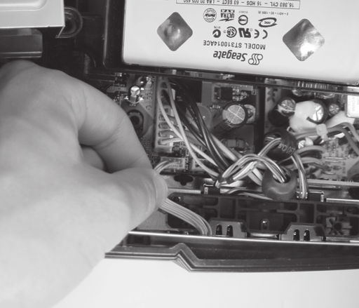
Figure 3-3: Detach the front panel wire connector from the Xbox motherboard.
Three friction locks hold the front panel in place: one on either edge of the front panel, and one in the middle poking through the metal electromagnetic interference shield. First, loosen the friction locks on the edge using a thin-bladed flathead screwdriver as shown in Figure 3-4. These locks are very tight, and you may have to release it in sections, starting with the top section. Insert the screwdriver tip into the space along the side between the panel and the main case body, and pry until you feel a slight give. Remove the screwdriver and repeat the process near the bottom of the case. You may need to try several times before the lock is free. Do not apply excess force to the case, as you could crack or nick the plastic. When the edge of the front panel is free, you will be able to flex it away from the case. Repeat this process for both edges.
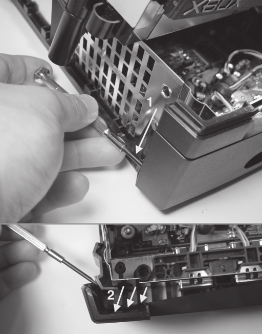
Figure 3-4: Loosen the edge friction locks with a flathead screwdriver. (1) Start working from the top and move down; (2) once the panel is free, it should bend outward from the case.
Once both edges are free, pull up on the middle friction lock (shown in Figure 3-5), and the front panel should pop off.
Once the front panel is free, thread the front panel wire connector through the hole in the metal electromagnetic interference shield and lay the panel flat on a table with the outer face down.
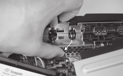
Figure 3-5: The thumb is pressing on the middle friction lock.
Removing the Front Panel Circuit Board
The front panel assembly of the Xbox contains a small circuit board, held in place with a single friction lock retaining clip, as shown in Figure 3-6. Use a finger or a screwdriver to push down on the friction lock and pull the front panel circuit board assembly out of its cradle.
Lay the circuit board assembly on a table with the green side down. You should see two clear LEDs and two flat push-button switches.
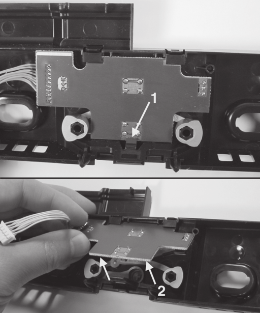
Figure 3-6: Lift the printed circuit assembly out of the front panel. (1) Push down on the friction lock tab, using a screwdriver if necessary, (2) then lift the assembly out of the front panel.
Installing the Blue LED
Now that the circuit card assembly has been removed, it is time to install the blue LED. This will require some soldering, so plug your soldering iron in and let it heat up. Keep in mind that it is important to use a soldering iron with a fine tip and to use soldering iron tip cleaner to condition the tip before using it. See Appendix A, “Where To get Your Hacking Gear,” if you need any of these items; you can equip yourself for just a little more than the cost of a video game.
Remove both existing LEDs with a flush-cutting wire cutter. Preserve as much of the metal legs coming out of the LEDs as possible because you will use them to attach your blue LED later on. Figure 3-7 shows how the circuit board should look when you are finished.
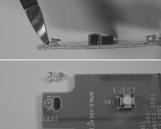
Figure 3-7: Cut the existing LEDs off the circuit card assembly. (Top) cut the LED as close to the case as possible; (bottom) the LED removed. Use this procedure to remove both LEDs.
To assist with soldering, tape the circuit board down to a flat surface with a piece of masking tape, so that it does not move. Position the blue LEDs so that their legs touch the metal stubs of the old LEDs on the circuit board assembly. (Figure 3-8 shows how to identify the polarity of an LED and their proper orientation on the circuit card assembly. See the sidebar “The Anatomy of an LED” if you are unsure about how to identify the polarity of an LED.)
Tape the lens portion of the LEDs in place with masking tape so they do not roll around while you solder them. You wil need to bend or cut the legs of the LED that will be installed on the right hand side of the board because the yellow wire connector will be in the way.
Warning

Pay careful attention to an LED’s polarity. If you install an LED backwards, no light will be emitted. See the sidebar on the Anatomy of an LED if you are unsure how to identify the polarity of an LED.
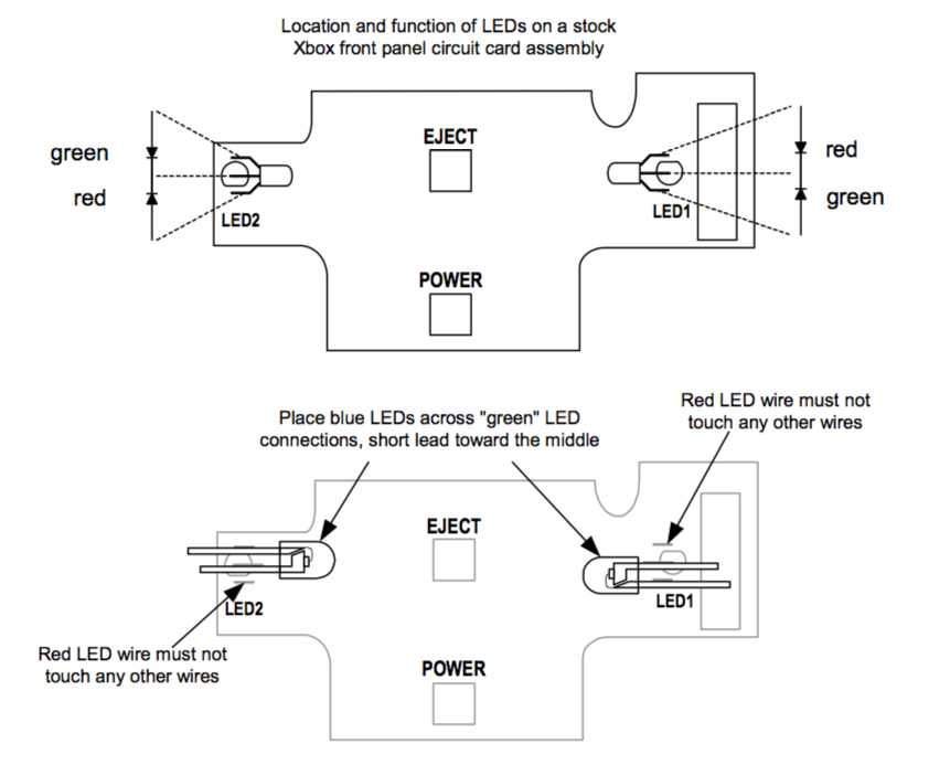
Figure 3-8: Placement of the blue LEDs on the front panel circuit board assembly. Note the anti-symmetry of the LED colors on each side of the circuit board.
Figure 3-8 also illustrates the polarity and function of the stock Xbox LEDs. Adventurous readers are encouraged to improvise and install multiple LEDs or surface-mount LED packages to try and get more colors and functionality. It is possible to install LEDs that are slightly larger than the T-1 package used in the Xbox by first sanding down the edges of the LED.
Once you have double-checked the LED polarities and verified that the short lead on both LEDs is abutting the remains of the original LED’s center lead, solder the LEDs in place. Figure 3-10 shows the LEDs being soldered in place. (If you have never soldered before, you may find it helpful to read Appendix B, “Soldering Techniques” before proceeding.)
Before using the soldering iron, melt a little bit of solder wire to verify that the tip is sufficiently hot. The solder wire should melt instantly if the tip is hot enough. If the soldering iron is too cold, you will not be able to form a good joint and you run the risk of damaging the circuit board.
Hold the hot iron tip against the blue LED’s lead and push the lead into the metal stub on the circuit card assembly. While the lead is heated, apply a touch of solder wire to the point where the blue LED lead meets the metal stub. The molten solder’s surface tension should cause the solder to wet the blue LED’s leads and the metal stub on the circuit board assembly. If this does not happen, remove the iron and apply a little bit of flux to the joint, and try again.
The Anatomy of an LED
LEDs, or light emitting dodes, are polarized devices, which only allow current to flow in one direction. This means that they will not work when put in backwards. Figure 3-9 illustrates the anatomy of an LED. The shorter lead on the side of the LED package with a small flat is called the cathode. The cathode must be connected to a potential more negative than the other lead, the anode, in order for the LED to function.
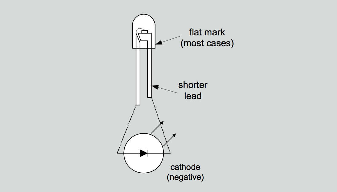
Figure 3-9: The anatomy of an LED.
Different LEDs characteristically require a different amount of forward voltage to turn on. Red LEDs typically require 1.7 volts, green LEDS require about 2.1 volts, and blue LEDs require 3.5 volts and up. Early blue LEDs required almost 5 volts of forward voltage, but advances in technology have decreased their voltage making them easier to integrate into battery-powered and low voltage electronics. When shopping for an LED for this project, be mindful of the required forward voltage. If you install a 5 volt blue LED, its light output will be very dim, since the maximum forward voltage generated by the Xbox drivers is around 3 volts.
Do not hold the soldering iron tip against the metal stub for extended periods of time or it will melt the solder that holds the stub in place. You will know that the stub’s solder joint to the board has melted, when the stub starts to sway freely. If this happens, hold the soldering iron tip against the board and slowly drag the soldering iron tip away. Dragging the tip will prevent the stub from getting pulled out of the board with the iron. Wait for the stub to cool and bend the stub back into position.
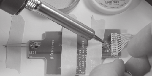
Figure 3-10: Soldering the LEDs in place. Note how the board and the LEDs are taped in place using masking tape.
Once you have soldered all four connections on the two LEDs, clip off the excess LED leads as short as you can without cutting the metal stubs. The finished board should look similar to Figure 3-11.
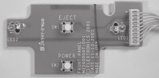
Figure 3-11: Finished board assembly.
Reassembling the Front Panel
Snap the circuit card assembly back into the front panel by aligning the top edges beneath the retaining clamps and pushing the card into the friction lock.
Now, take the full front panel assembly and mate it to the Xbox. First, feed the wire connector through the original oval-shaped hole through the electromagnetic interference shield. Then, push the front panel into the Xbox, and all three friction locks should snap into place.
Reattach the front panel wire connector to the Xbox motherboard. The connector is shaped so that you can only insert it in one direction, but the plastic used in the connector molding is soft and you could insert it backwards if you push hard enough, possibly causing irreversible damage to it. Verify the correct orientation by lining up the missing pin on the board receptacle with the missing wire on the connector header, as shown in Figure 3-12.
If you have an older Xbox, re-attach the vertical circuit board assembly by pushing it into its sockets. This circuit board is the interface card for the Xbox game control ers, so you’l definitely want that installed correctly.
Now, you are ready to test your newly modified front panel assembly. Replace the disk drives in their bays and verify that their power cable and ribbon cable connections are secure. Plug the Xbox in and you should be treated to a blue glow coming from the Xbox front panel. (If you don’t see what you expect, don’t panic. The next section, “Debugging,” offers solutions to some possible problems.)
Once you are satisfied with the modification of your Xbox, turn the Xbox off and replace the four retaining screws on the front panel assembly. (You wil need to remove the disk drives again to access the screw holes.) Replace the disk drives, power up the Xbox one more time to verify that everything is working fine, and then reassemble the rest of the Xbox as described in Chapter 1.
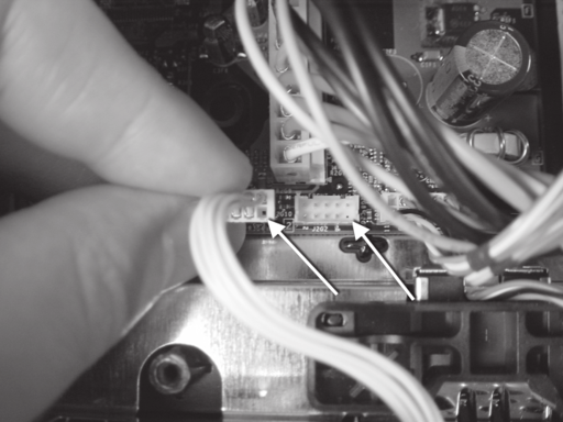
Figure 3-12: Orientation features of the front panel wire connector. The arrows indicate the position of the empty polarizing pin.
Debugging
Sometimes things go wrong. In my experience, something going wrong is more often the case than not. The most important thing to remember if something doesn’t work is, don’t panic! Keep your wits together, make observations about what is going wrong, and try to hypothesize the cause the malfunction. For your reference, Table 3-1 contains a list of common problems and their possible causes. Appendix E, “Debugging: Hints and Tips,” contains a more in-depth discussion of debugging techniques.
| Problem | Possible Cause |
|---|---|
| Xbox does not turn on. | • Front panel wire connector not properly inserted. • Xbox not plugged in. • Front panel wire connector damaged, or front panel circuit card assembly damaged. |
| Xbox turns on and functions properly, but no light comes out of the LEDs or only half of the light circle around the eject button is lit. | • One or more LED installed backwards. • One or more LEDs installed on the red LED's metal stubs, instead of the green LED's metal stubs. Verify this by turning on the Xbox without the video cable plugged in. This will cause the Xbox to send a flashing signal to both the red and the green LEDs. |
| Xbox turns on and sequences through initial animation, but the console indicates that it needs service. | • Hard drive or DVD connectors have come loose. Verify that the gray ribbon cable header is fully inserted into each drive and that the power connector for each drive is fully inserted. • On older Xbox models, check that the vertical game controller interface board was re-installed properly. |
| Xbox turns on, but game controllers do not respond. | • On older Xbox models, check that the vertical game controller interface board was re-installed properly. |
| Xbox turns on but DVD does not eject. | • Verify that the wire connector between the front panel and the Xbox motherboard is properly inserted. • Verify that the DVD power connector is properly inserted. |
Table 3-1: Debugging guide for installing a blue LED.

