Chapter 8: Converter Nodes (N)
The converter nodes are very versatile. They usually are small tools, but I don’t think I could imagine Cycles without them. They allow you to do math, change vectors, split tuples and so on. So in a word precise fine control.
Math (M)
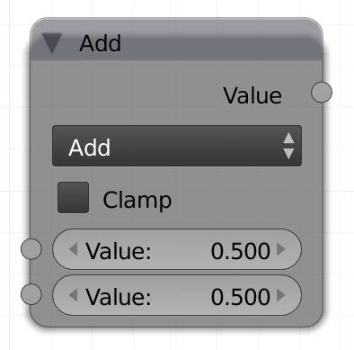
The math node lets you transform the input value by most of the common mathematical operations. It is usually not used to transform a single value, since that could be done with a calculator, but to transform a black and white image or information light or values. You can also use colors as inputs for this node, but only their value (lightness) will be taken into account and the end result will be a grayscale map. It has two values as input, which again can be a single value or a grayscale map. You can also type in “e” or “pi” into the value field, to input the Euler constant or pi.
All trigonometric calculations use radians.
Add
Adds one value to the other.
Of course it is not relevant which value goes into which socket. Use this to raise the minimum influence a map has on a factor.
Subtract
Subtracts the lower value from the upper value. Use this to decrease the maximum influence a map has on a factor.
Multiply
Multiplies two values.
Of course it is not relevant which value goes into which socket. It is most commonly used to increase the strength of a factor. It is often better suited than add, because 0 stays 0 in this transformation, so the blacks will not be affected.
Divide
Divides the upper value by the lower value.
The influence on the displace of a material output node can get ridiculously high very quickly. Use this to lower the effect, by dividing by 5 or higher.
Sine
This mode will calculate the sine of the upper value while ignoring the lower one. The values are treated as radians.
Cosine
This mode will calculate the cosine of the upper value while ignoring the lower one. The values are treated as radians.
Tangent
This mode will calculate the tangent of the upper value while ignoring the lower one. The values are treated as radians.
Arcsine
This mode will calculate the arc-sine of the upper value while ignoring the lower one. The values are treated as radians.
Arccosine
This mode will calculate the arccosine of the upper value while ignoring the lower one. The values are treated as radians.
Arctangent
This mode will calculate the arctangent of the upper value while ignoring the lower one. The values are treated as radians.
Power
The upper value is the base, the lower one will be the exponent of this operation.
Hint: use this instead of multiply for smoother gradients.
Logarithm
This will calculate the logarithm of the upper value to the base of the lower value.
Hint: For the natural logarithm use the letter ‘e’ for the lower value.
Minimum
It compares the two values and outputs the lower one, thus allowing no pixel to be brighter than the value specified.
Maximum
It compares the two values and outputs the higher one. Thus allowing no pixel to be darker than the value specified. So if you want to limit the strength of a map, plug it into the upper socket and enter the maximum value you want to allow in the lower one.
Round
It rounds the upper value, ignoring the lower one.
Most values you will encounter are between 0 and 1, in this range values less than 0.5 will become 0 and everything else will become 1.
Less Than
This node compares two values and will output white where the upper value is lower than the lower one. It does not allow for any value between 0 and 1.
Greater Than
This node compares two values and will output white where the upper value is higher than the lower one. It does not allow for any value between 0 and 1.
Modulo
Will divide the upper by the lower value and return only the rest.
If you are not a programmer, modulo is one of the lesser known operations. It returns the rest of a division only. So 13 divided by 3 is 4 with a rest of 1, since 3 * 4 is 12, 1 too little. Therefore 13 modulo 3 will return 1, 12 modulo 3 will return 0 and 14 modulo 3 will return 2. Less mathematically speaking a modulo node with 5 in the lower socket will count from 0 to 4 and then start over again.
ColorRamp (C)
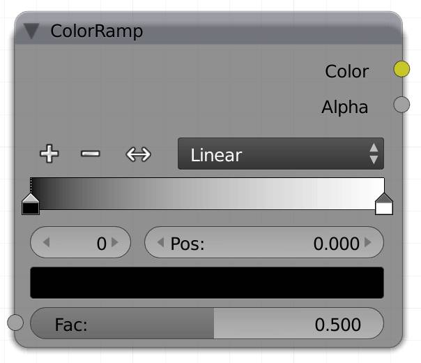
This ramp is very useful to control the contrast or shift the spectrum of a grayscale map. Whatever is 0 (dark) in the input will be converted to the color on the left hand side of the ramp, 1 will be influenced by the value on the right hand side, and everything else by the ramp that is calculated in between the two. This operation is called interpolation. The sliders with color field are called stops.
Each stop can have an RGB and an alpha value. Eventual alpha contained in your input image will be treated as black and returns the color on the leftmost side of the ramp.
You can either drag the stops to control their location, or click on one and type its location between 0 and 1 into the Pos field. The number to the left of that field is the index of the active stop, starting at 0.
The color field below those values is split, but you can only recognize this if you actually used the alpha slider in the color picker to use an alpha value smaller than 1. The left hand side shows the color value, the right one the alpha value. By clicking on it you can adjust the RGBA values of the active stop.
By clicking the plus sign you can add as many control stops as you like, the new one will be created exactly in the middle of the active one and the one to the left of it. If the active one is the last one to the left however, the new stop will be created to the right. Minus will delete the active stop.
You can mirror the color ramp by using the double arrow next to the plus and minus.
You can set the interpolation mode between two stops to the following :
Linear
Linear interpolation means, if you are on a ramp between 0 and 1, going 25% to the right will result in a value 25% brighter, than where you started.
Ease
This will create a smoother transition than linear .
B-Spline
This will result in a very smooth transition, but the color influence will surpass the individual stops, like the handles of a Beziér curve influence the values before and after the center point.
Cardinal
I'm really sorry for this, but when I was researching what the cardinal does exactly, I read the Wikipedia article about cardinals in mathematics, and I just had to put the explanation here:
“ In mathematics, cardinal numbers, or cardinals for short, are a generalization of the natural numbers used to measure the cardinality (size) of sets. The cardinality of a finite set is a natural number – the number of elements in the set. The transfinite cardinal numbers describe the sizes of infinite sets. ” - Wikipedia.org
So, we clear? Here is my interpretation, that does not require a minor in mathematics to be understood:
It creates a ramp with a transition that is more subtle than ease , but less than b-spline .
Constant
In this mode there will be no transition between two colors, starting from the left, wherever the next stop is, this is where the next RGBA value starts.
Fac
Input your texture or factor here. As indicated by the gray dot, color information will be ignored and only the brightness of the color will be regarded.
Since Blender 2.72 there are two modes of this node to make it easier to pick from multiple colors without using multiple stops. You can choose between HSL and HSV color space to transform a value along the colorwheel.
The color space does not determine the range from which the Colors can be picked, but only how they are calculated internally. So as long as you don’t use calculations, like HSV, color mix or color ramp nodes, there will not be much of a difference for you.
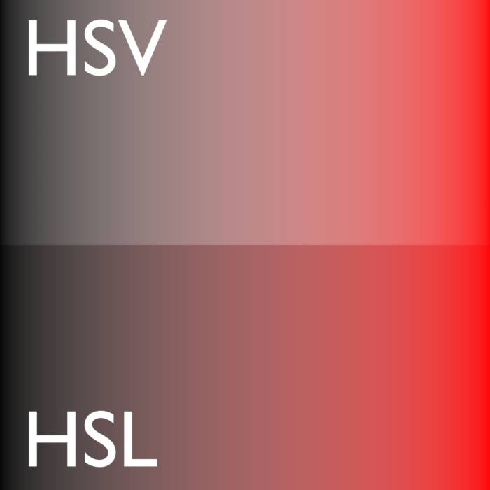
| HSV The h ue s aturation v alue transition uses the same color space you can pick in the Blender color wheel for the calculation. |
| HSL The h ue s aturation l ightness transition uses HSL for the calculation, which conserves the brightness of a color when transitioning from dark to bright and vice versa.
Transitioning between colors of equal brightness looks the same for both color spaces. |
You can choose the progression along the color wheel:
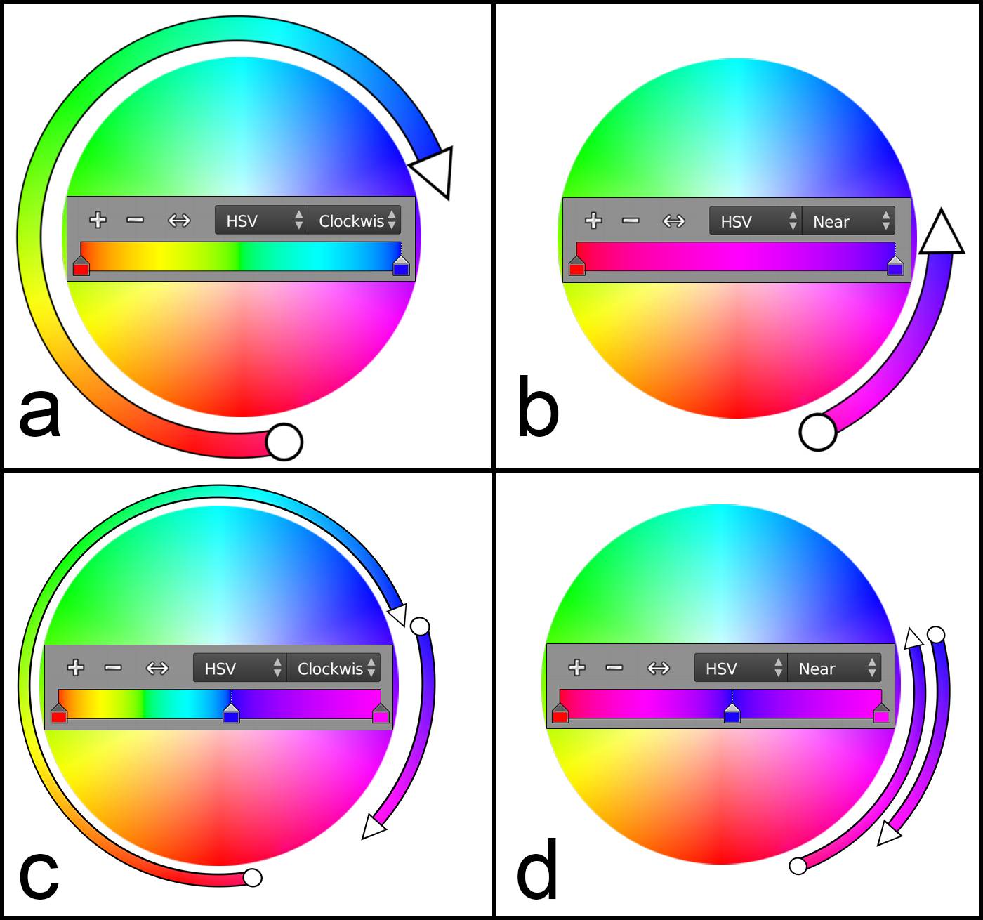
Fig. 8.1) Different versions of converting values into colors using the color ramp node. The circle represents the color of the 1., the arrowhead the 2. stop of the ramp. In the In the upper row clockwise (cw) and far, as well as counter-clockwise (ccw) and near produce the same results.
a) going cw along the color wheel.
b) going ccw along the color wheel.
Second row: If there is more than one stop, there can be a difference between cw / ccw and near / far.
c) between all stops the orientation is cw along the wheel.
d) both ranges are going the shortest distance along the wheel resulting in one going ccw and the other cw.
Clockwise
The transition between stops will be clockwise around the color wheel.
Near
The transition will pick the shortest distance between the stops, either clockwise or c ounter-clockwise.
Counter-Clockwise
The transition between stops will be counter-clockwise around the color wheel.
Far
The transition will pick the shortest distance between stops, either clockwise or counter-clockwise.
At this point you might ask yourself what the difference between clockwise and near if both methods can send the picker along the wheel in the same direction. There are two situations where there can actually be a difference.
- If you are using multiple stops, then set to near or far the node will pick the direction between each pair of stops individually, where for example clockwise will set the same direction for each pair.
- If you are animating the colors of the stops, choosing near or far can make the direction flip in each frame.
Color
This outputs the converted colors from the fac input. By default this is black and white, but you can assign colors to each stop, which will influence the output color.
Alpha
The alpha output will ignore the color and output a grayscale map, where the brightness represents the alpha value of each point.
The alpha of the input image is ignored. Only if you set one or more sliders to an alpha value smaller than one with the color picker this output will not be entirely white.
RGB to BW (R)
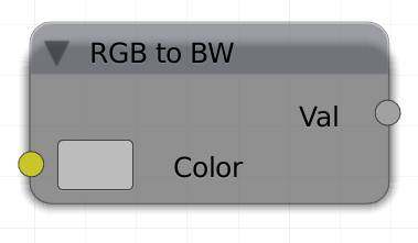
The quickest way to desaturate an image. Plug it into the color input and get the black and white result at the output.
Vector Math (V)
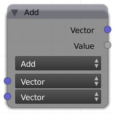
This node lets you transform a vector. The difference to the regular math node is that a vector in our case consists of three values, so there are several transformations unique to vectors, while others will just use regular math on all three values.
Vector
A three dimensional vector, consisting of three numbers.
Hint: You can also use vectors as colors, their X, Y and Z values will be treated as the R, G and B.

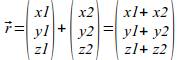
Add
The most simple method. It will add the three values of the lower vector to the corresponding values of the upper vector.
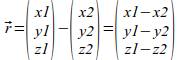
Subtract
It will subtract the three values of the lower vector from the corresponding values of the upper vector.
Dot
This method is also called scalar product. It uses the two vectors and returns a single number, by combining the 6 values as follows:
Let's call the upper vector v1, and the lower vector v2. If you scalar multiply two vectors, you will get this equation:
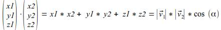
Where α is the angle between the two vectors.
Why is this useful? Because if you scalar multiply two vectors with this node, you will get a value between -1 and 1, depending on the angle between those vectors, it will be 0 if they are orthogonal, 1 if the are parallel and -1 if they are antiparallel, meaning they are pointing in opposite directions. All other angles will fall between those values, e.g. an angle of 45° will output middle gray.
Note: it will output a single value in the Fac socket, not a vector.
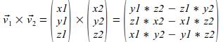
Cross Product
If you cross multiply two vectors, the resulting vector will be perpendicular to both input vectors.
2 vectors can span a plane, therefore the direction of the normal of a face can be calculated by the cross product of the direction of any two of the edges. The math works as follows:
Let's call the upper input vector v1 the one of the lower vector v2.
Then
Normalize
A vector has both a direction and a magnitude. The magnitude can be regarded as how far you go into the specified direction. If you use normalize your vector will keep its direction, but gets a length (magnitude) of 1. The math works as follows:
The length L of a vector V is:
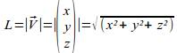
So if you want your vector to have a length of 1 you need to divide each value by L. Any vector can be normalized this way:

Since all values get divided by the same number, the ratio of x : y : z stays the same, therefore the direction of the vector is not altered.
Note: This method will ignore the lower input.
Separate RGB
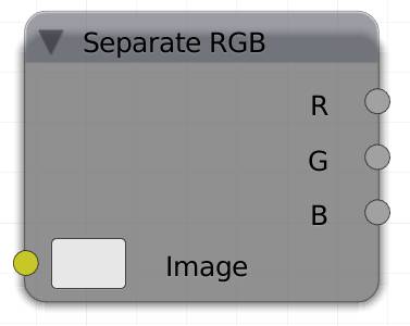
The separate RGB should be used with a colored image as an input otherwise you could just enter the R,G and B values manually.
From each pixel it will analyze the red, green and blue parts and split them into three different values, depending on their individual intensity.
White for example will output 1 in each socket. From top to bottom perfect blue will output 0, 0, 1.
Hint: This node is very useful if you want to use different maps on the same object. You can paint one part in red, one in blue, one in green, and leave one black. This way you can create four maps on one texture, saving you a lot of RAM.
Image
Input texture to be separated. I'm saying texture instead of color, because it does not make too much sense to input a single color here.
R
Returns the red values of the texture
G
Returns the green values of the texture
B
Returns the blue values of the texture
Combine RGB (I)
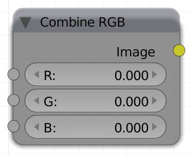
This node takes the three values given and combines them into a single color.
So let's say it receives 0 red, 1 green and 0.5 blue this would result in the color 00FFBC, which is a greenish turquoise. For more details on how R, G and B get combined see .
R
Input for the red value of the color.
G
Input for the green value of the color.
B
Input for the blue value of the color.
Color
The color calculated by the combination of the input values.
Separate HSV (H)
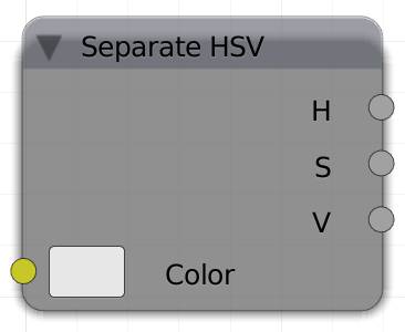
There are several methods for how to define or describe a color. A couple of them have already been mentioned above. The three most important ones are those that you can choose from, if you click on a color field of a node. Below the wheel you will see the options , HSV and value.
For this node, I will concentrate on hue saturation value. If you adjust the hue, your color picker will rotate around the center of the color wheel. If you decrease the saturation, your picker will be drawn closer to the center and the value will adjust the lightness bar to the right of the color wheel.
You can use this node to split a texture into maps representing these values. Each pixel has an HSV information that can be expressed in values between 0 and 1 for each of them.
H
Returns the hue value of a color.
S
Returns the saturation of a color.
V
Returns the lightness of a color.
Combine HSV (O)
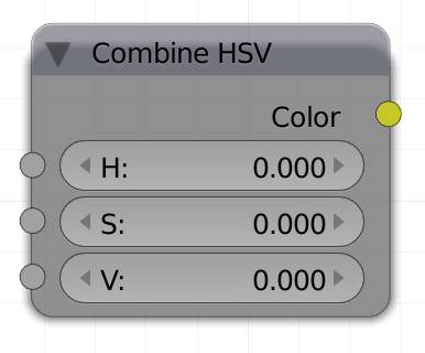
Just as you can separate a color into its HSV values (see above), you can use this information to also create a color by inputting its HSV information. All inputs should be values between 0 and 1.
H
A value for the hue of the outgoing color.
S
A value for the saturation of the outgoing color.
V
A value for the lightness of the outgoing color.
Color
The combination of the H, S and V input as an RGB.
Separate XYZ (Z)
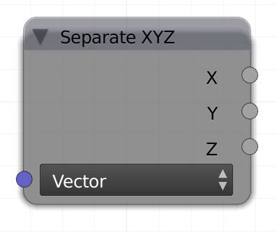
The Separate XYZ node can be used to split a vector into its individual values. Separating these values into black and white information allows you to do interesting things, like coloring an object based on its location or making particles glow more the higher they fly.
Each channel will output the actual value of the position, not its absolute, so on an object with an X location of -6, the corresponding output will be blacker than black.
Vector
Input a vector here, the most commonly used one is probably a Location.
X
Outputs the X value of the input vector.
Y
Outputs the Y value of the input vector.
Z
Outputs the Z value of the input vector.
Combine XYZ (I)
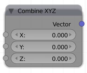
With this node you can combine black and white information to form a vector. This vector will be generally used as the input for a texture, but you can also do other things with it, like the . You can - for example - split a vector into X, Y and Z with the separate XYZ node, transform each channel individually, using math or textures, and recombine the result.
X
Input value which will be used as the X – value of the output vector.
Y
Input value which will be used as the Y – value of the output vector.
Z
Input value which will be used as the Z – value of the output vector.
Vector
Outputs a vector with the X, Y and Z value from the according inputs.
Wavelength (W)
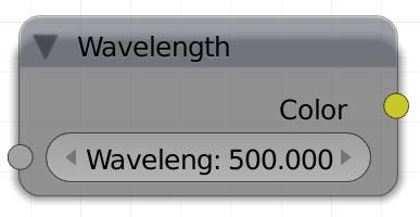
This node will convert the wavelength of a light ray to an RGB value. In nature light hitting a surface will be both absorbed and reflected. White light consists of all visible wavelengths from 380 to 720 nanometers.
Part of the light hitting the surface will be absorbed and only the remainder will be reflected. The composition of the reflected light will result in the color we perceive. Use this node if you know the wavelength of the color your object is supposed to have, to convert it to a value the Cycles shaders can understand.
Here are the most important values:
Red: 640 - 720 nm
Green: 495 - 570 nm
Blue: 450 - 495 nm
Purple: 380- 450
The wavelength in between two colors results in a mix of them.
Wavelength
A value between 380 and 720 nm, which is the spectrum we can perceive.
Color
Outputs an RGB Value.
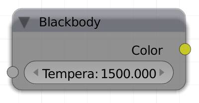
Blackbody (B)
If you are not interested in physics, you can skip this paragraph.
Trivia: A blackbody is a hypothetical object that absorbs all light independent of the frequency, wavelength or anything. Since this does not exist in reality, astronomers use the term blackbody temperature when analyzing the light emitted from a distant object, like a star or a planet. It is just assumed that the light reflected from these objects is not strong enough to interfere with the results over such a great distance. The temperature of the object affects the wavelength and thereby the color of the emitted light. The blackbody temperature is specified in Kelvin, which has the same stepsize as Celsius (where water freezes at 0° and boils at 100°), but starts at absolute zero, where no particles are moving, which would be slightly below -274° Celsius. It correlates with the wavelength of the electromagnetic radiation (light).
For light emitters we assume that they don't reflect light, because it will be minute compared to the light they emit. Their temperature is measured in Kelvin. Higher values will make a light source – the blackbody - seem colder or more blueish. Our sun is about 5780° Kelvin on the surface. This node will convert a given temperature to an RGB value. This can be useful for an interior you may need to construct, where the architects tell you the blackbody temperature of all the lamps, or to let Cycles calculate the light colors in a fire simulation.
Note: A mesh light with a lower temperature and a high strength may look white to the camera, but the warmth of the light stays the same. You can think of this effect as overexposure.
Temperature
The temperature of the blackbody, lower values < 1000 will output red, 3000 is a pale orange, 5780 is the temperature of sunlight – or more precisely the surface of the sun, whereas values > 6000 will produce a pale blue.
Color
RGB value output.

