Python is a very popular programming language for use with the RP3, and in this chapter you will be presented with the information you need to start using Python 3 on your RP3 with the GPIO pins. If you are used to programming in Python, you will still want to read this chapter to learn how it interfaces with the GPIO.
First Things First
Before you can jump in you need to access the GUI. You can do this by pressing Ctrl-Alt-F2. Once you’ve done that, go to Menu … Programming … Python 3. This will open up the Python 3 shell, where you can enter instructions a line at a time.
Basics
Let’s start with a very basic program At the >>> type this command:
print(“Hello, world!”)
And then press Enter. You should see this appear on the screen: Hello, world!
Interfacing via the GPIO
For this example, we are going to use a Python program and a simple circuit to turn an LED on and off. The circuit you need to build is pictured below. Notice the red wire connects to power and the black wire connects to ground. This should be built on a solderless breadboard to take advantage of the power and ground columns.
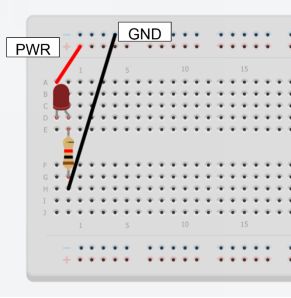
Make sure that the line or wire from wiring pin #7 ties into the long, or positive lead, of the LED. The resistor, on the other hand, should be tied into the short (negative) lead of the LED with the other end attached by a line/wire to wiring pin #9, which is one of the ground pins for the 3.3V side of the GPIO pins.
Now that you have your circuit setup, you are ready to program. For this, we won’t use the shell but rather the Python IDLE development environment. To access it, you will need to go to the terminal/command line and type sudo idle. This will open up the Python Shell in superuser mode. Superuser mode gives you access to the GPIO pins.
Once you are in the Python Shell, go to File … New … Widow. You will then be in IDLE. This lets you write programs, make changes to them, run them, etc.
What follows it he program you need to type in – exactly as it is written:
import time
import RPi.GPIO as GPIO
GPIO.setmode(GPIO.BOARD)
GPIO.setup(7,GPIO.OUT)
GPIO.output(7,True)
time.sleep(5)
GPIO.output(7,False)
Now let’s take a moment to talk about what the code is doing. We start by importing Python’s time library so we can access a sleep command to make it leave the LED on for 5 seconds.
The next imppot command gives us access to the RP GPIO library, and treats the GPIO board as an object named GPIO.
The command GPIO.setmode(GPIO.BOARD) means that you will be referring to the pins using their wiring number (the way they are numbered on the board – see the chapter on GPIO).
GPIO.setup(7,GPIO.OUT) sets pin 7 as an output pin. That means you will be making changes to its value, rather than just reading it to see what value it is set to.
GPIO.output(7,True) means that you are changing GPIO pin 7 to output to true (think 1, high, or on). This allows current will pass through it to the LED, then through the LED to the resistor, and then back to ground. This will cause the LED to light up.
The time.sleep(5) command tells the computer to wait 5 seconds before running the next command. The next command turns off any current through pin 7, changing it to low or off. The LED should now go off.
Once you have typed everything in and made sure there aren’t any typos, you are ready to run the program. Go to Run … Run Module. You’ll be prompted to save your program, so give it a descriptive name so you’ll remember what it is fore. We saved the file as blinker.py
When the program runs, the LED will light up for five seconds and then turn off. We have just controlled an electronic component by programming a computer.
Online Resources:
Overview of Python:
Python RPIO Documentation:
The Python Game Book:

