2: Basic Valve Theory
The basic principle of valves is quite simple. American parlance calls them
vacuum tubes, electron tubes, or simply ‘tubes’. The correct technical terminology is a Thermionic Electron Device (TED), but nobody actually calls them that today. Valves are electrostatic devices that utilise electron flow, the basis of all electric current flow. The basic start of the electron flow process begins with an element within the valve envelope called a cathode. The abbreviation often used is the lowercase letter k in diagrams.
All materials are made up from individual atoms, whether they are conductors or insulators. The atom is itself made up of several different parts. At the centre of the atom is the nucleus, which contains the major part of the mass. Contained within the nucleus is the proton, which is a positively charged particle. Around the nucleus, negatively charged particles are in orbit, called electrons. The number of electrons depends on the atomic element: hydrogen has only a single electron while metals have many more electrons in orbit. The electrons are mobile and can freely swap orbits with their neighbouring atoms. When an electron changes orbit, it leaves a deficiency in that particular atom. For a brief period the atom is positively charged and is searching for a companion electron to balance the charge. In no time at all another wandering electron passes by, it is attracted by the positively charged atom, and the status quo is restored.
Metallic materials have electrons hovering very close to the surface, like a fine mist. They can be easily attracted away by a sufficiently positively charged object. At room temperature the electrons are a bit sluggish and do not have the ability to leap far from the parent metal. However, if the metal is heated to a high temperature they become much more active. When the temperature is high enough, the electrons have high energy and can be imagined as a thick fog hovering over the parent metal. (This is similar to steam over the surface of boiling water.) However, they soon lose energy and fall back to crash land on to the metal surface. At any one time, there are a finite number of electrons ‘in space’ above the metal surface. How many is determined by the temperature of the metal. (Some very special materials emit large numbers of electrons even at room temperature. These were used to make special valves, called cold-cathode valves. But today these are rare).
This in simple terms is what constitutes a cathode. It is a source of ‘free electrons’ which have parted from the parent body for a short time. If a positively charged object is now brought close to the metal the free electrons will jump ship and cling to the object. Pure metals are not the best source of free electrons, unless the temperature is very high. There are, however, some other materials which liberate electrons much more freely. These are certain oxides of rare earth materials, such as barium, thorium and strontium. If the parent metal is coated with these oxides the generation of free electrons increases dramatically.
The positively charged object has a special name; it is called the anode. It is also a metallic material. If an external voltage is applied between the anode and the cathode, we can make electrons flow between them, even in a vacuum. As with magnets, there is a certain relationship. With magnets “like poles repel, but unlike poles attract” and the same occurs with electrons. Being a negatively charged particle it is repelled by another electron, or negatively charged object, however it will move towards a positively charged body. Electrons behave like magnets with an attraction force.
If the distance between the electron and the positively charged body is large the attraction force is small. As the electron begins to move towards the positively charged body it is initially travelling slowly, then as the distance reduces the attraction force becomes greater. Before very long they are travelling at a speed approaching the speed of light, typically 70%. When the electron reaches the anode, it is travelling very fast and collides with the anode. Although the electron is very low in mass, it does have some. Because it is travelling so fast, when it strikes the surface of the anode it gives up the kinetic energy it has accumulated as it accelerated.
This dislodges other electrons, which are already at the surface; it is like dropping a stone into a pool of water. The displaced electrons, although now catapulted into the space above the anode, are strongly attracted because they are very close to the anode and they return to the anode in a very short period. This displacement of electrons due to a collision is called secondary emission.
The kinetic energy released when the electron slams into the anode at close to the speed of light causes heat and this raises the temperature of the anode.
The unit of electric current is the Ampere and it consists of electrons moving from one point to another at a certain amount per unit of time. 1 Ampere of current is the result of:
~6.25 x 10¹⁸ electrons per second.
This is a very large number.
The number of electrons that can be generated is a factor of the cathode coating, the temperature and the surface area. It is common to classify cathode electron emission in terms of mA per area in square centimetres. A typical chart of emission is shown in Fig 2.1.

Fig 2.1: Cathode emission chart.
The cathode temperature is in Kelvin above absolute zero. Tungsten has the lowest emission at low temperature. To emit sufficient electrons it needs to be heated to a very high temperature. The oxide-coated cathode needs the lowest temperature and the thoriated-tungsten cathode lies in between these other two types. Thorium is a rare earth metal commonly used as a coating on tungsten wire.
For maximum emission of an oxide-coated cathode, the temperature is about 1350ºK; the thoriated-tungsten cathode is about 1900ºK. Tungsten cathodes are bare wire and need to be at 2700ºK for best emission. Bright white is about 3300ºK. Tungsten is the material that electric lamps are made from and a tungsten cathode runs at a similar temperature. They are very bright! In valve terminology they are classed as ‘bright emitters’.
Normally when electric current flow is considered, we say that the current flows between the positive terminal and the negative terminal, the so-called conventional current flow. In reality, it is the other way round. Unfortunately, when this convention was adopted the scientists were not aware of electron flow and they got it wrong!
We can see from the chart that an oxide-coated cathode can supply ~2A of current per square cm. This is about the upper limit with modern technology.
The cloud of electrons on the cathode surface gives rise to other terminology that is used. The cloud of free electrons is known as a ‘space cloud’. As the anode attracts some of the electrons away from the cloud, replacements arise from the cathode so that at any one time there is a relatively constant number awaiting transportation to the anode. If the rate of production of free electrons is not sufficient, the maximum anode current cannot be achieved. The stream of electrons moving between the cathode and anode are called the ‘space charge’.
How a valve is made
Early experiments with primitive valves largely used the same methods that the electric incandescent lamp designers used. In the search for a filament that gave long life, it was found that the use of fine tungsten wire gave the best performance. The wire used is very thin, typically less than the thickness of a human hair, and when at operating temperature they are extremely fragile. It was found that operating a tungsten filament in air gave a short life as the wire rapidly evaporated at the temperature required to give sufficient light output. The use of an evacuated glass envelope solved the problem and protected the filament. Hence, a new industry arose of mass-produced glass envelopes encapsulating the filament, with suitable lead-out wires to connect to the current source. When valve experiments first started it was a spin-off of the electric lamp technology and used the same methods to encapsulate the parts into a glass envelope. The earliest valve experiments simply used incandescent lamps with extra parts added, with lead-out wires through the glass envelope, often on the sides for convenience.
It was found that to eliminate the air from the glass envelope it was necessary to suck out all the air to produce a high vacuum. Consequently, when valves first became available they were commonly known as ‘vacuum tubes’.
Within the glass envelope, the various parts are usually supported on stiff wires and the parts are built up on these as a foundation. Those parts that must be electrically isolated from others were supported by thin mica sheets and the support wires served as a means of carrying the various voltages and current to the parts. The wires exiting the glass envelope pass through the glass and are bonded to form a hermetic seal so that no air can be sucked in.
Although the vacuum pumps suck the vast majority of the air from the envelope, it is not possible to create a perfect vacuum. A few molecules of air therefore still exist, which causes a problem when the voltage used is very high. This causes ionisation of the gas remnants and a consequent arc to occur. To cure this problem a system called a ‘getter’ was developed.
The getter is a small piece of barium wire or tape mounted inside the envelope, often on a small ring of nickel. This is heated by either passing a large current through it, using spare pins on the envelope, or by inducing a large current in the wire by an induction coil. When the barium ignited it burnt only as long as there was air to support the combustion. When all the air was grabbed, it formed a silvery coating on the inside of the glass envelope. This coating, throughout the life of the valve, serves to capture any gas that is emitted from the hot metallic parts and prevent an ionising cloud forming. (Some graphite anode valves have the getter element embedded in the anode material.) The getter is so named because it “gets the last few air molecules”. The getter is normally ignited after the tube pinch-off has been sealed when the vacuum pump has pulled the air out of the envelope.
Diode
This basic concept allows us now to examine the first of the valve types. This is the diode. Di come from the Greek for two and the ode part is the contraction of electrode. Therefore, a diode is a two-electrode valve (not a Welsh two-line poem!)
By connecting a diode in series with a source of AC voltage and a load resistor, we can form a simple rectifier. On the positive half cycle the electrode connected will attract electrons whereas the other electrode is now negatively charged. Hence, electrons will flow between the cathode and the anode when the anode is positive with respect to the cathode. On the opposite half cycle the cathode is positive and it attracts all the electrons. The anode in this state is negatively charged and the electrons will not be attracted towards a negatively charged object. Hence, the simple diode acts as a half wave rectifier and can be used to convert AC into DC. Today semiconductor diodes use the same naming terminology, anode and cathode; it is a throwback to the valve era.
It is interesting to ponder on certain words and their meaning. The verb ‘to rectify’ means ‘to correct’ or ‘put to rights’. One can only wonder if the inventor of the name for the rectifier considered there was something wrong with AC and it needed to be corrected into DC!
The basic valve rectifier circuit is shown in Fig 2.2. The simple half-wave rectifier is shown in Fig 2.2(a).
As well as single diodes there are multiple diode valves. A full-wave rectifier is shown in Fig 2.2(b). Often these are two or three separate diodes in one envelope. Some types for three-phase rectification had as many as six individual diodes to form a full-wave three-phase rectifier. Rectifier valves were made in various voltage and current ratings to suit different types of equipment in use. A small domestic wireless receiver might only require an anode current supply of about 100mA at 300V DC, others might require higher currents and voltages. Initially rectifier valves used 4-pin, 5-pin or 8-pin bases: the last of these was known as the octal base. Often the glass envelope was bonded into an insulating base with metal pins; later types used full glass envelopes, omitting the insulating base.
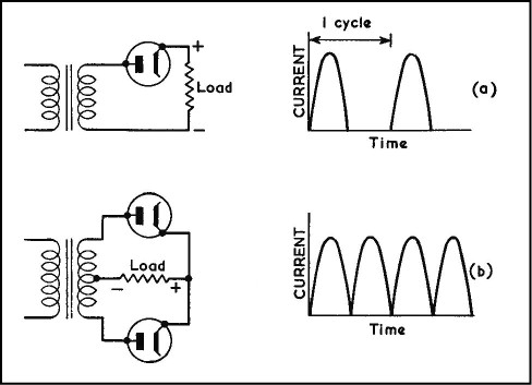
Fig 2.2: Valve rectifier circuits.
Valves were easily removable as the base pins plugged into sockets on the equipment. Hence, it is quick and easy to replace a faulty valve. The pins are polarised so that the valve can only fit if the pins are correctly lined up with the sockets. Some types, such as the octal and the later Loctal based valves, have an additional polarising spigot to guide the valve pins into the socket, making it simpler to insert the valve.
The next valve in the logical series has an extra part, called a grid. This has three electrodes, and is called a Triode.
Triode Valve
In the triode, the anode and cathode are similar to the simple diode type. The extra electrode is placed close to the cathode, while the anode is a similar distance away as in the diode type. This new electrode is called a grid because it uses a grid of fine wires to form a screen between the cathode and the anode. Although the grid has very small apertures, compared with an electron they are gaping holes. Hence, the electrons have little difficulty finding their way between the cathode and the anode.
The common form of construction is to use concentric cylindrical tubes. The cathode is the smallest tube. Around this is the control grid, wound as a helical coil or a series of mesh grids rolled up into a hollow tube. The anode is the outer tube, which forms the support, via stiff pins and mica insulators, to hold the various cylinders in the correct alignment.
The crux of the grid, which is called the control grid, is that it gives us a means to control the flow of electrons from the cathode to the anode. It acts in the same way as a water tap. In hydraulics and pneumatics, a device used for controlling the flow is called a ‘valve’ and this is why valves are called valves! When the valve is fully open, maximum flow occurs, but if the valve is partially closed, the flow is diminished. When the valve is shut no flow occurs.
The control grid of a triode allows control of the flow of electrons by varying the voltage applied to it. Electrons, being negatively charged particles, abhor any other negatively charged object. By applying a sufficiently high negative voltage to the grid the electrons in the space cloud are repelled and form a tight cluster on the surface of the cathode. When the grid is not so negatively charged, some of the electrons are able to pass through the grid because the high positive voltage on the anode is attracting them. If the anode voltage is raised and becomes more positive the attraction also increases and more electrons will pass through the grid. Hence, raising the anode voltage also creates a greater current flow.
If the grid voltage is raised to equal that of the cathode, the voltage difference falls to zero. It behaves as if the grid had been completely removed. In this state maximum anode current will flow. If the grid voltage is raised so that it becomes positive with respect to the cathode then another state applies.
The electrons are looking for a positively charged place to go. It matters little if it is the anode or some other positively charged object. With the grid now very positive, and it being much closer to the cathode than the anode, some of the electrons will land on the grid in the same way as they land on the anode. This means that the amplitude of anode flow begins to fall as a large number of electrons pass to the positive grid structure. If the grid is sufficiently positive, it reduces the anode current flow to a very low level. The current now flowing in the grid causes it to heat up as the very fine wires have a high resistance. This can lead to damage if allowed to become too high.
In between the very high positive grid potential condition, and only a weakly positive condition, another factor comes into play. The electrons leaving the cathode are initially attracted by the very high anode potential. As they travel towards it, they also experience the attraction of the weakly positive control grid. This extra attraction serves as a ‘booster rocket’ to start the electrons on their way. When the electrons reach the grid they are already travelling at nearly full velocity. They fly on by and as they get further away from the grid, now travelling to the anode, they experience less and less attraction from the weak grid positive potential and more and more from the anode. The small positive charge, if it is not too high, acts as an initial accelerator to the electrons. Above this weak condition, the grid will attract more and more electrons until the anode is starved of electrons. Hence, when the grid is a few volts above zero the anode current actually increases before falling off.

Grid structure of the 2C39A triode.
The scheme in valve design is to maximise the acceleration of the electrons and to minimise the number that get arrested by the grid. Of course, some electrons will always fail to pass through the fine grid structure, simply because they collide with it. As long as the number that impact on the grid is small, no harm is done. As with the anode, when an electron slams into a static object it causes heat as it gives up the kinetic energy it contains. So some very small grid current will always exist, although the grid is not positively charged. The amplitude of this current is so low it is barely measurable. For the case where the grid voltage is negative, but not enough to completely cut-off the anode current, the electrons bend around the charged wires and avoid them. They are like a slalom skier twisting and turning to avoid the poles.
A typical grid structure is shown to the right. This is from a small microwave triode (2C39A), the grid is the classic crossed wire type and the spacing from the cathode is only ~0.25mm. The anode spacing is ~1.2mm away from the grid, so the electron flight path is very short. The valve anode portion has been broken off to see inside the valve. The glass envelope is a simple round tube.
The grid wires are about 0.01mm diameter and the aperture between the wires is about 0.05mm. The dark object in the centre is the cathode surface. The grid wires are stretched taut and spot welded to the washer shaped outer which connects to the grid contact.
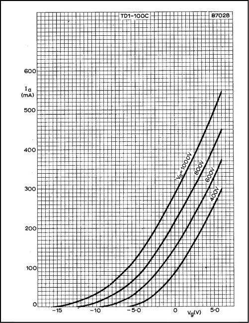
Fig 2.3: Triode anode current curves (from Mullard Technical Handbook, Book 2 Part 4, ‘Valves and Tubes’, 1969).
The anode current curve of a typical small transmitting triode is shown in Fig 2.3. In this chart there are two main axis, one being the grid voltage (X-axis) and the other being the anode current (Y-axis). The various lines are the result of different grid-cathode bias voltages at different anode voltages. This set of curves is for the 2C39BA triode manufactured by Mullard under their part number TD1-100C.
The vertical axis shows the anode current value in mA. The horizontal axis shows the grid to cathode voltage. The four curves each correspond to different anode voltages. This type is the simplest anode current curve. Fuller details are contained in a later chapter, where we will analyse other types of curves in detail, and how they are used.
From the chart, we can establish certain things. The anode current flow is directly related to both the anode voltage and the grid voltage. If the 400V anode current curve is examined, to bring the anode current to zero requires a grid-cathode voltage of
–6V. To find what anode current flows for other grid voltages when the anode voltage is 400V, then we can pick another point on the 400V curve. Assume we choose 100mA. We then drop a vertical line down to intersect the horizontal axis and read off the scale to find the required grid voltage. It is +0.5V. Similarly, we can establish any other anode current versus grid voltage by using the chart. To drive the valve up to 400mA when the anode voltage is 1000V we find it needs to be +2.6V. To cut-off the anode current for this anode voltage requires
–16V.
You will notice that the curves really are curves, not straight lines. This is because, in most valves, the transfer characteristics are distorted at very low and very high current. The only straight parts of the curves are above a certain minimum anode current and below some maximum anode current. The upper anode current curve on this chart do not go high enough to see the curving at very high anode current. At very high anode current, the limitation to anode current flow is purely the ability of the cathode to produce sufficient electrons. When the cathode cannot deliver enough electrons then the anode current curve will flatten out.
Tetrode Valve
The next valve commonly used includes yet another extra electrode, and since it now has four electrodes, it is called the tetrode.
The triode valve can be improved and the tetrode was the next logical step. In the triode, when the electrons slam into the anode they tend to dislodge other electrons and cause secondary emission. These dislodged electrons cause a ‘confusion’ of the total electron flow between the cathode and anode and can be detrimental to the operation. If another grid structure is placed close to the anode, and positively charged at a voltage well below the anode potential, it will arrest the secondary emission electrons and help to clean up the total flow. This new grid structure is called a screen grid or Grid-2. It sweeps up any errant secondary emission electrons and diverts them away from the anode back to the power supply.
In doing so, a small additional current exists in the new grid structure. Under normal operation this current is fairly small. However, if the anode voltage is lowered towards the potential of the screen grid the latter begins to act like another anode. If the anode voltage falls to be equal to the screen grid voltage then we now have two similarly polarised ‘anodes’ fighting for the electrons in transit. Hence, the screen grid voltage should never be as high as the anode, or conversely, the anode voltage should never fall lower than the screen grid voltage.
There are, however, valid exceptions to this rule. If the screen grid and the anode are connected together, the tetrode valve becomes a simple triode. This is sometimes done for various reasons which will be covered later.
One of the actions of the screen grid is not only to arrest errant stray electrons but also to behave in the same way as a slightly positive control grid. It causes an additional thrust to the electrons travelling between the cathode and anode to give then a little extra acceleration on the final part of the flight path. The result of this is that, not only does the control grid have major control on the number of electrons released to fly towards the anode, but now also the screen grid has the same effect. It acts like a subsidiary control grid. When the two are acting in unison the result is that the electron flow is increased. Hence, the screen grid tetrode valve has a greater current flow than a similar size triode. This means that for a certain variation of control grid voltage there is a greater change in anode current flow. It is about three to five times greater than a similar size triode valve.
However, the tetrode also has a certain drawback. Being an additional structure placed between the control grid and the anode, the screen grid can also experience secondary emission effects, because some of the high velocity electrons can impact, and cause more secondary emission electrons to be present. To correct this problem another grid structure is used. Hence, we now have a valve with three grid structures, the Pentode.
Pentode Valve
The Pentode introduces the final grid and this is called the suppressor grid or
Grid-3. This grid is placed between the screen grid (Grid-2) and the anode, but it is connected to the cathode. This is either an internal connection or one the user has to connect at the valve base pins.
Being at the potential of the cathode, the electrons see it as another structure with the same potential as they are. Hence, they try to avoid it, and rather take safe haven somewhere more positive. This safe haven is awaiting them; it is the screen grid. So the suppressor grid suppresses the errant secondary electrons from the anode and forces them to take refuge in the screen grid.
Of the two types of screen grid valves, the tetrode and the pentode are both very similar in characteristics. Many and varied are the different internal construction techniques used, but they all work much the same way. Pentodes and tetrodes both have higher current gains than triodes. In certain applications it is preferable to use a pentode and in others a tetrode. Tetrode and pentode characteristics can also be adapted to suit different applications by changing the size, spacing or shape of the grid structures to cater for special requirements.
Beam Controlled Valves
In the constant search for a better valve, designers tried another approach. The pentode valve, although it works well, can also be improved. The basic problem was still the secondary emission effect, and a simple cure for this is to convert the grid structure of the suppressor grid into a funnel shaped plate close to the anode. This is also connected to the cathode and the result is that it serves to guide the electron stream towards the anode more accurately. These new plates are called beam forming plates, and were pioneered by RCA in America. They are quite large and shaped so that the electrodes want to keep away from them. They are effectively negatively charged of sorts, and adding these beam plates concentrates or focuses the electron stream on to the anode more effectively. They employ the electrostatic effect, as use in cathode ray tubes to focus the electron stream on to the phosphor-coated screen into a minute spot.
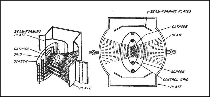
Fig 2.4: Beam forming plates (from RCA technical literature).
A diagram, taken from the RCA Electron Tube, book is shown in Fig. 2.4. The use of the beam forming plates gives much better performance and this breakthrough led to the new name of beam tetrodes, which are commonly used for high power valves in transmitters. Many of the classic transmitting valves are beam tetrodes and they give good performance with high efficiency at high frequency. Some of the early beam tetrodes were the RCA 807 and 813 transmitting valves, of which millions were produced during WWII and after. Other common beam tetrodes used by amateurs are the RCA 6146 and its derivatives, the Japanese 6JS6C and the Mullard / Philips QQV0 twin-tetrode series, popular for use at VHF / UHF.
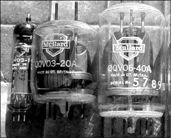
The Mullard QQV0 series of dual tetrode valves, left to right: QQV03-10, QQV03-20 and QQV06-40.
Other multiple electrode valves
Apart from the types already mentioned there are three other types that are used for special purposes. These are generally receiving type valves and are used in mixers and other frequency conversion circuitry.
The three other valves are the hexode, heptode and the octode. As the names suggest, they are six-electrode, seven-electrode and eight-electrode types. The additional electrodes are more like the control grid than a screen or suppressor grid. In frequency mixers, they allow another signal also to vary the anode current flow. In a mixer, the valve is usually operated in a highly non-linear manner. This is necessary, as without non-linear characteristics a mixer cannot work.
Cathode-Filament construction
There are several different cathode structures used. Some are plain tungsten wires, often oxide coated, and serve as the heater and the cathode combined. These types are commonly used in large rectifier valves and some RF triodes and are known as directly heated cathodes. Other types use a heating filament within a tube, which is coated on the outside with an oxide. These types are known as indirectly heated cathodes (Fig. 2.5). Many small receiving and transmitting valves use the indirectly heated cathode: they simplify the design but have a finite voltage breakdown at high heater to cathode voltages. The directly heated cathode does not have this problem, but it makes the design of the equipment more difficult.
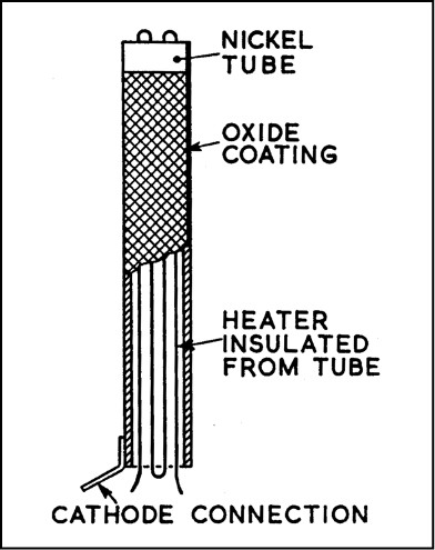
Fig 2.5: Indirectly heated cathode construction.
Generally, all cathode heaters require an AC or DC filament supply. In large transmitting valves, the power consumed by the filament can be quite high. The Eimac 3-500Z triode, for example, requires a 5V-filament supply of 14.5A for each valve. If the amplifier has two valves the filament supply has to supply almost 30A.
The most common method of supplying the filament is a low voltage winding on the mains transformer. If the equipment uses different filament voltages, a winding for each different type is required. Small receiver and low power transmitting valves often use either 6.3V or 12.6V, so they suit mobile radio operation from a 12V car battery supply. Other types have dual voltage filaments. These are usually two filaments connected in series with a centre tap pin. These can use either 6.3V or 12.6V by wiring the base pins accordingly.
In American valve numbering often the first number denotes the filament voltage, for example a 6SA7 and a 12SA7 are the same valve except one has a 6.3V filament and the other a 12.6V filament. For television and radio receivers often all the valves have the same filament current, for example 300mA, and they can be wired in series and supplied from the AC mains supply with a suitable dropper resistor in series.
Envelope Construction
The vast majority of smaller valves use a type of glass envelope. Some glass envelopes are a quartz-glass mixture, which withstands high temperature better. Other types use what appears to be a metal envelope, but most of these smaller valves are simply a normal glass envelope with a protective metal outer cover. A diagram of a typical small valve is shown in Fig. 2.6.

Fig 2.6: Internal construction of a small valve.
A picture of some typical valves is found on the next page. The two on the left are different variants of the same valve and both have the octal base. One is the earlier type, which is glued on to the glass envelope; the metal shrouded one has the later composite octal base and polarising spigot. The two smaller all-glass valves have the vacuum seal on the top as a small glass pip. The silvery getter coating can be seen at the top of the middle valve.
To the right is a picture looking inside a typical transmitting valve, to show the grid construction. This is a Mullard QQV06-40 with the outer envelope removed and without the anode plates.
The wire grid visible is the screen grid. Behind it is the control grid and the indirectly heated cathode structure. The rectangular mica plate at the right has two holes to align the two anode plates. The base-screening ring is partially visible at the left. The metal supports around the central portion are the beam forming plates. On the top are the two cross-coupled neutralising ‘flags’.
Anode Dissipation and Cooling
For each type of valve there is a safe operating temperature and anode dissipation. Dissipation is rated as watts of power dissipated in the anode. The valve needs to be kept below a certain maximum temperature for long life and reliable operation. There are several different ways that the anode gets rid of the heat dissipated and it varies from type to type.
In small glass envelope valves, it normally is a mixture of radiation and conduction. Infrared heat will pass through a vacuum and arrive at the outer glass envelope, which then gives off the heat to the surrounding air. In low power valves, often this is sufficient to keep the valve cool. Some larger valves anodes glow dull red at maximum output, as a way of increasing the infrared cooling effect. In some other types heat travels up the anode support wires and exits to the pins, where it can be heatsinked, either via the base socket wiring or, in the case of top cap anodes, with special finned cooler attachments. Other types require forced air cooling blown on the envelope or through a finned cooler. Some very large transmitting valves need liquid cooling to dissipate the heat.
The manufacturers normally state the maximum safe dissipation and recommended maximum envelope and seal temperature to ensure reliable operation. It is important to pay attention to these recommendations to achieve the maximum life of the valve.
For large transmitting tetrode valves it is not only the anode that dissipates an appreciable amount of power, but also the screen grid. If operated at an unsafe temperature it will often lead to catastrophic failure. If the temperature reaches the softening temperature of the glass envelope the high vacuum has been known to cause the envelope to implode by sucking in the soft glass.
Generally, there is no danger in over-cooling a valve, and it can give a significant improvement in the life. Eimac gives some data on valve life with temperature values for glass envelope valves. For example, a lowering of the glass envelope temperature by as little as 25ºC below the maximum can increase the life by 25%. A 50ºC reduction almost doubles the life.
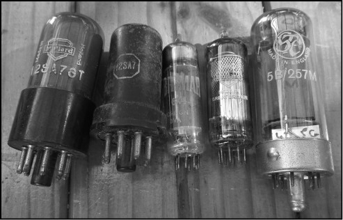
A selection of different valve types.
For valve equipment that uses cooling fans, it is especially important to ensure that any air inlet or outlet vents are not covered, for example by placing a log book etc on the cabinet. Also, the fans and air vents should be checked regularly for any build up of dust, also ensuring that the motor turns freely and that it is lubricated as per the manufacturer’s instructions. The volume of air flow should also be checked regularly to assess the efficiency of the cooling. The air outlet temperature is a good indication of whether the valve is receiving sufficient cooling.
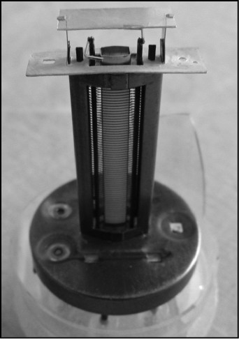
Internal details of the QQV06-40 twin tetrode valve.
Efficiency
Any device, when converting energy from one form to another, always suffers some loss or inefficiency. Valves are no exception to this rule. For each watt of DC input power it is unreasonable to expect the same power output. How much of the DC input power will be converted into the output is defined by the efficiency.
Generally, we use the simple formula:
Efficiency η (Greek letter eta) = power output / power input x 100%
Of the various operating modes some are more efficient than others. For RF amplifiers the best is Class C, next is Class B and the worst is Class A. Exactly how well each operating mode can convert the DC input power to the output power can be calculated from first principles. And here is where the subject becomes interesting.
For many years the topic was clouded by a chart that originally appeared in a textbook which showed the theoretical value of efficiency that would be possible with an ideal valve / tube. This is reproduced in Fig 2.7.
Fig 2.7: Theoretical efficiency for various conduction angles. (From Thomas L Martin Jr, ‘Electronic Circuits’, Prentice-Hall Inc, 1955.)

However, this chart and the calculations made an erroneous assumption. The assumption was that the valve was able to swing the anode voltage over a range equal to the DC supply voltage. This means the anode voltage would swing down to zero volts and up to twice the supply voltage. There is no known valve that can operate in this manner. It is virtually impossible to swing the anode voltage down to zero volts, even using a large triode type.
Consequently, the upward swing cannot be greater than the downward swing for a resonant anode circuit that is tightly coupled to the load to transfer the maximum power. In a Class C amplifier the conduction angle is normally not less than about 60º, and very often greater needs to be used, up to about 150º, and this requires a gross amount of drive to attain. If this method were used the drive power required would be excessive and the grid dissipation would be destructive. In practice the minimum conduction angle is about 90 to 120º. So, although the chart shows that a Class C amplifier can attain 100% efficiency, in practice it does not. If one considers the theoretical 100% point on the curve then the conduction angle is 0º which is impossible to attain. Although, with very high power pulsed amplifiers the conduction angle may approach 45º, the space between pulses is long and the average grid current is then fairly low.
Terman [1], however, did calculate the theoretical limits with a valve behaving in the correct manner, under what would be considered normal operation. The values he calculated have stood the test of time and been proven to be correct for the case of the ideal valve. He gave the value for a Class C amplifier as 84% maximum, Class B as 78.5% maximum and Class A as 25% maximum. The in-between classes of AB1 and AB2 are 50% and 55% respectively. From many tests these values are well proven when practical amplifiers are examined. However, in a practical amplifier we never achieve the ideal conditions, so the numbers are always a bit lower.
Notes
[1] Frederick Emmons ‘Fred’ Terman (1900 – 1982), was Professor of Electrical Engineering, Dean of the School of Engineering, Stanford University, USA. He wrote two standard text books, Radio Engineering, first published in 1932, and Electronic and Radio Engineering in 1955.

