two 12V DC relays are used to interchange AC electricity to the contactors of the motor which manipulate its path (either Up or Down). The circuit designed using Multisim is shown within the diagram underneath:
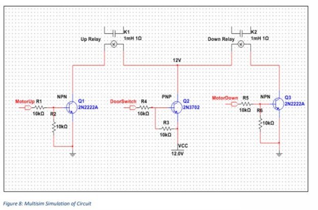
One cease of the coil contactor of each the relay’s are related to the 12V DC supply through a PNP transistor. the primary reason of doing that is to ensure that the Motor isn't always supplied energy until the raise door is closed. as soon as the lift door is closed, the DoorSwitch output pin to the gate of the PNP transistor is pulled to floor ensuring that the PNP is became directly to offer the VCC strength to both the relays. consequently the relay isn't became on even though the MotorUp or MotorDown signal is excessive. the alternative end of the relay coil is pulled to ground via a NPN transistor. The MotorUp signal is generated from the MCU. whilst the MotorUp sign is excessive, the primary NPN transistor is activated and it pulls the other coil contact to floor to complete the circuit to energy the coil of the Up Relay to electricity the motor. The identical method is used to set off the Down Relay. motives for the usage of transistors to replace the Relays are:
- Each relays have 12VDC coils, therefore it's far essential to apply a PNP transistor to exchange the high facet (12V) part of the coil because the MCU is best able to generating 5V which is not enough to show the relay coil on.
- Transistors can be used to switch on the relay by means of the use of minimum current from the MCU as little cutting-edge thru the base of the transistor turns on it. this protects power in the MCU when it wishes to interchange the relays.
- It additionally isolates the MCU from any back current that can float back to the pin of the MCU which could probably damage the MCU.

