The On/Off Timing for the outside load is configured in line with user's desire at some point of energy up.
there's simplest ONE enter user switch (besides RESET) and ONE OUTPUT RGB LED.
The trick is to use the equal transfer as:
- PRESS & release right away Mode
- PRESS & maintain DOWN Mode
Off Time represents the period while the external load will stay powered off, which may be a aggregate of seconds, minutes & hours.
On Time represents the length even as the outside load will live powered up, which may be a combination of seconds, minutes & hours, too.
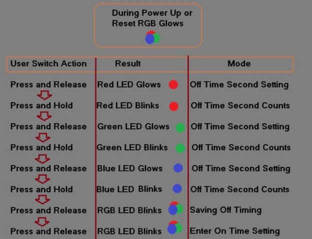
right here is the begin up sequence to configure the device:
After the Off-Time is set, a similar process is needed to observe to set On-Time.
when placing is complete, the LED will blink in colors to represent general off and on time so the person can affirm.
right here are the policies for the RGB LED glow/blink:
the primary blink is constantly disregarded. After first blink in each shade:
- consecutive crimson blinks count as Seconds
- consecutive green blinks matter as minutes
- consecutive Hours blinks matter as Hours
Off-time is set first, then press and release to enter on-time (RGB all blinks). On-time is about subsequent (similar to off-time placing method). when putting is completed, the LED blinks to confirm off-time and on-time inside the respective colorings. each off and on time setting are shown separated with the aid of RGB blinks in among them.
E.g. think I want to prompt time of five Sec, 4 Min, zero Hrs: i can do 6 pink blinks, 5 inexperienced blinks and 1 blue blink. See the motion video for better understanding.

