5.3 Demo Analog Input (ADC): Working with Potentiometer
In this section, we learn how to read analog input on OpenMV board. For illustration, I use Potentiometer as analog input source. Our scenario is to read analog value from Potentiometer. Then, display it on Serial tool.
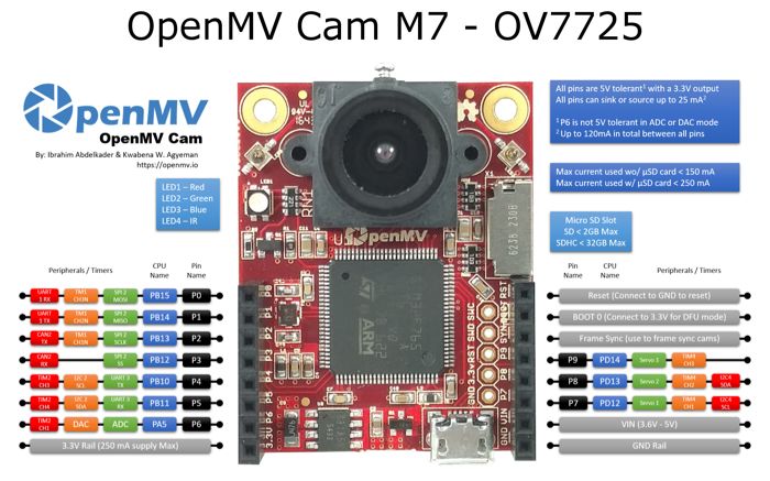
OpenMV has several ADC pins that you can see it above. If you want to work with many analog input, you must expand it using ICs based ADC. In this section, we are working on OpenMV ADC on P6.
Let's start!.
5.3.1 Wiring
To understand Potentiometer, you see its scheme in Figure below.
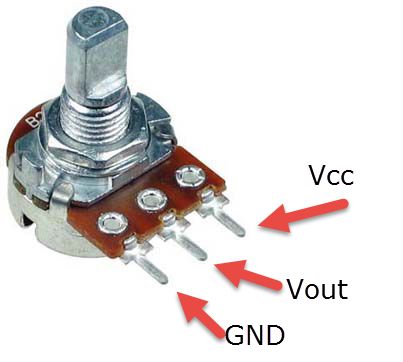
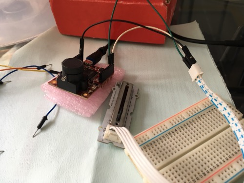
You can connect VCC to OpenMV board on 3V3 pin (VCC +3.3V). Vout to OpenMV board Analog input ADC (P1). In addition, GND to OpenMV board GND. The following is hardware implementation. I use slide potentiometer.
5.3.2 Writing Program
We use ADC object, , to read from analog. Value analog input is 0 - 4049.
Firstly, open OpenMV IDE. Write the following codes.
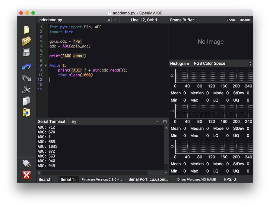
from pyb import Pin, ADC import time gpio_adc = 'P6' adc = ADC(gpio_adc) print('ADC demo') while 1: print('ADC: ' + str(adc.read())) time.sleep(1000)
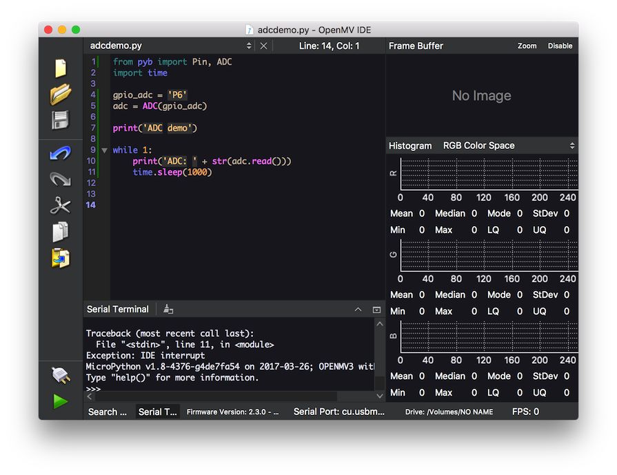
Save this program as adcdemo.py file.
5.3.3 Testing
Run the program and open serial output to see program output. The following is program output:
