5.2 Demo Analog Output (PWM) : RGB LED
In this scenario we build a program to control RGB LED color using OpenMV Analog output (PWM). RGB LED has 4 pins that you can see it on Figure below.
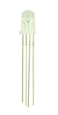
To understand these pins, you can see the following Figure.

Note:
- Pin 1: Red
- Pin 2: Common pin
- Pin 3: Green
- Pin 4: Blue
Now we can start to build a program and hardware implementation.
5.2.1 Wiring
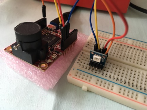
For our testing, we configure the following PWM pins.
- RGB LED pin 1 (red) is connected to OpenMV pin P0
- RGB LED pin 2 is connected to OpenMV 3V3 (VCC +3.3V) or GND (Depending on your RGB Led anode or cathode)
- RGB LED pin 3 (green) is connected to OpenMV pin P1
- RGB LED pin 4 (blue) is connected to OpenMV pin P2
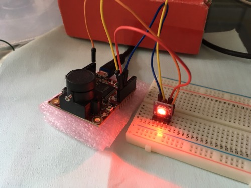
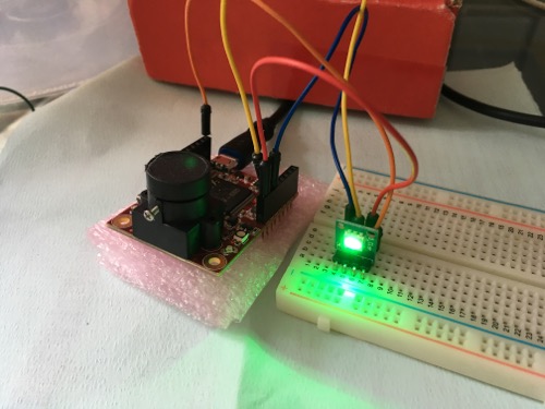
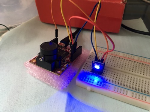
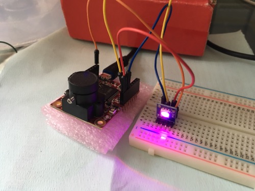
Here is a sample implementation with OpenMV and RGB Led.
5.2.2 Writing Program
To display a certain color, we must combine colors from red, green, blue. OpenMV provides API for PWM using Timer and TimerChannel, http://docs.openmv.io/library/pyb.Timer.html. We set PWM value with input value from 0 to 1023.
Regarding to Timer pinout, here’s the Timer Pinout:
- Timer 1 Channel 3 Negative -> P0
- Timer 1 Channel 2 Negative -> P1
- Timer 1 Channel 1 Negative -> P2
- Timer 2 Channel 3 Positive -> P4
- Timer 2 Channel 4 Positive -> P5
- Timer 2 Channel 1 Positive -> P6
- Timer 4 Channel 1 Negative -> P7
- Timer 4 Channel 2 Negative -> P8
Let's start to build a program in OpenMV IDE. The following is complete code.
from pyb import Pin, Timer import time gpio_red = Pin('P0') gpio_green = Pin('P1') gpio_blue = Pin('P2') def set_rgb(red, green, blue): tim1 = Timer(1, freq=1000) ch1 = tim1.channel(3, Timer.PWM, pin=gpio_red) ch1.pulse_width_percent((red*100)/1023) ch2 = tim1.channel(2, Timer.PWM, pin=gpio_green) ch2.pulse_width_percent((green*100)/1023) ch3 = tim1.channel(1, Timer.PWM, pin=gpio_blue) ch3.pulse_width_percent((blue*100)/1023) time.sleep(1500) tim1.deinit() print('print PWM with RGB led') while 1: print('red') set_rgb(0, 1023, 1023) print('green') set_rgb(1023, 0, 1023) print('blue') set_rgb(1023, 1023, 0) print('yellow') set_rgb(0, 0, 1023) print('purple') set_rgb(700, 1023, 700) print('aqua') set_rgb(1023, 0, 0)
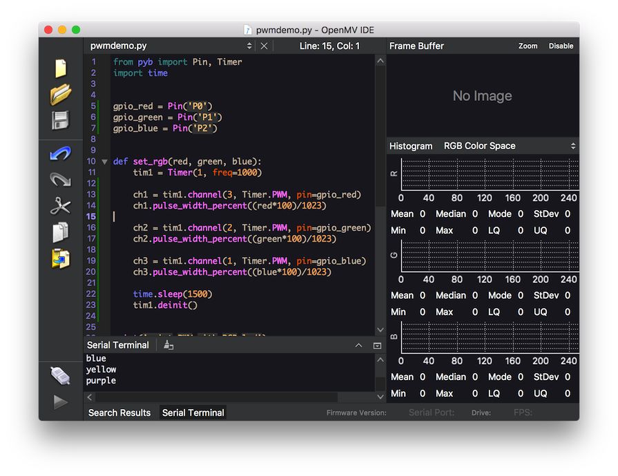
Save this program.
This program will generate six colors: red, green, blue, yellow, purple, and aqua.
5.2.3 Testing
Run the program. You should see several color on RGB LED.
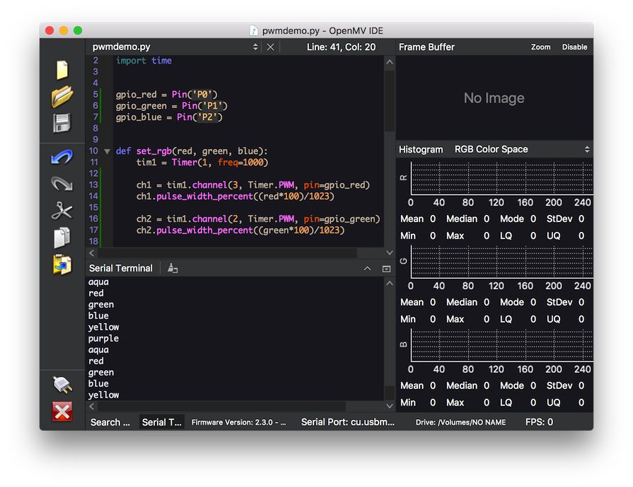
The following is a sample demo on RGB LED.
