Chapter 1 -
Voiding the Warranty
Tools of the Trade
Hardware hacking may seem daunting at first because of the sophisticated tools that are required for some projects. Fortunately, most basic projects can be accomplished with only a small investment in tools, comparable to the price of one or two video games. Appendix A, “Where to Get Equipment,” contains a suggested list of starter tools and instructions on how to order these tools.
This chapter will talk about basic tools you will need for serious hardware hacking, including tools to open things up, attach and remove electronic components, diagnose and probe circuits, and design circuit boards. Of these tools, good quality versions of the first two can be purchased at fairly reasonable prices. Diagnostic and test tools such as oscil oscopes and logic analyzers are worth their weight in gold, but you’ll find that these are very heavy and they wil be a formidable investment. As for circuit board design tools, some of the best tools can come at surpris ingly affordable prices.
This chapter will conclude with a step-by-step pictorial tutorial on how to open up the Xbox. More experienced hardware hackers can skip the next couple of chapters.
Tools to Open Things Up
The first step in hacking anything is getting the cover off. Most electronic appliances can be opened with just a set of Phillips and flathead screwdrivers, but the most interesting boxes will require a set of special security bits.
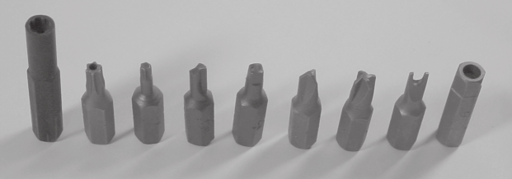
Figure 1-1: A selection of security bits. From left to right: Nintendo 4.5mm, security torx, standard torx, clutch, Robertson or square, tri-wing, torq, spanner, and security allen or hex.
Figure 1-1 shows a lineup of some common security bits. Surprisingly, security bit sets are affordable and easy to obtain. MCM Electronics (www.mcmelectronics.com) sel s a 105-piece security bit set (MCM order number 22-3495) for under twenty dollars, and a 32 piece set (MCM order number 22-1875) for under ten dollars. They are well worth the investment. Nintendo security bits are sold separately. You can get the large Nintendo security bit, used in the Nintendo Gamecube, for a few dollars (MCM order number 22-1150, “4.5mm Security Bit”). A smaller version of the bit (MCM order number 22-1145, “3.8mm Security Bit”) is also used in the older Nintendo systems and their game cartridges.
The Xbox uses standard torx (six-pointed star) bits of the T10, T15 and T20 size. These bits are fairly common and can be purchased at hardware stores such as Home Depot. You may also find a magnetic extension bit holder handy for reaching into a couple of tight spots around the hard drive and DVD drive in the Xbox.
Do not use excessive force when taking the cover off equipment. If you think you have removed all of the screws but the cover is still stuck, most likely you have either missed a screw, or you need to depress some friction lock tabs. Too, many times screws are hidden beneath the rubber feet on the bottom of equipment, or under a sticker label. To find screws hidden by sticker labels, firmly rub the surface of the label. You will feel a soft spot wherever there is a screw underneath. (Breaking such a label to access the screw instantly voids the equipment’s warranty, but have no fear: Most equipment is designed to be serviced, so simply removing the cover rarely causes any damage.)
On occasion, you will encounter a stubborn assembly that refuses to come apart. If the cover or panel flexes open around the edges or seems to have some freedom of movement, there may be some kind of friction lock holding the cover on. Friction locks are typically tab-and-slot structures, shaped so that it is much easier to insert the tab than to remove it. In this case, locate the tab by observing where the case seems to be stuck, and push in on the tab with a small flathead screwdriver while gently pulling up on the case. If there are multiple tabs like this, insert a wedge of some kind, such as another screwdriver or a paperclip, to prevent the tab from re-engaging as you open the other tabs.
If the cover or panel refuses to move even slightly when you apply firm pressure, it may also be attached with adhesive or it may even be welded shut. For example, “wall-wart” power supplies (the square black boxes that you plug directly into wall outlets) are often sealed in such a fashion. Taking such a piece of equipment apart may mean you’ll never be able to get it back together into its original form.
Tools to Attach and Remove Components
Electronic components are attached to boards by soldering. When soldering, a low-melting-point alloy known as solder is heated and flowed around the metals to be joined. The solder and the metals form a local alloy. Once the joint cools, the components are electrically and mechanically connected.
The basic tools for soldering are a soldering iron, solder, flux, and desoldering braid. (A pair of fine-tipped tweezers is also quite handy for jobs that involve fine-pitch components or small parts.) A soldering iron is a hand-held tool that consists of a heating element and a tip; the tip is used to melt solder alloys through conduction or direct contact, unlike other tools that use hot gases or intense infra-red radiation. The kind of soldering iron tip required for optimal heat transfer depends upon the situation. For example, a flattened “chisel” or “conical chisel” tip will perform better than a simple pointed tip when soldering most small surface mount components.
There are also many grades of soldering irons. The cheapest ones cost around ten dollars and come with large, unwieldy tips and have no temperature control; they just get as hot as they can. Better soldering irons cost more and have a sensor that actively regulates the tip’s temperature. Temperature regulation makes the tool’s action more consistent, and extends the life of the tip. Better irons also come with a wider selection of tips that may include very fine ones, suitable for working with the tiny components found in most electronics today. For light use, a quality direct-plug soldering iron with a good tip is sufficient. However, if you plan on building boards and really getting into hardware hacking, a hundred dollars for a quality temperature-controlled soldering iron such as the Weller WTCPT or the Weller WES50 is well worth the investment.
Solders come in a wide variety. For most purposes, a eutectic Pb-Sn alloy solder wire with a no-clean or water-cleanable flux core is sufficient. Eutectic alloys are desirable because they go directly from a liquid phase to a homogenous solid. Kester is a major manufacturer of solders; their standard cored wire solders, Formula 245 and 331, are both pretty good. Formula 245 uses a no-clean flux, but if you like, you can use a cotton swab with some isopropyl alcohol to remove the residue. Formula 331 has a flux core that works on more materials than 245. However, with 331 you need to wash down the board with water soon after soldering, or the flux residue will become gummy and possibly interfere with circuit operation. Many distributors sell Kester solder; for example, Kester 24-6337-8802 (25-gauge Formula 245 solder wire in a 1-lb spool) is DigiKey (www.digikey.com) part number KE1410-ND. The kind of solder sold at most Radio Shack’s is also quite good for soldering, although their solder tends to leave a sticky black residue and require cleanup with organic solvents.
Solder can also come as paste, with tiny solder balls suspended in a flux matrix. Solder paste can be very useful when attaching fine-pitched surface mount components. (See Appendix B, “Soldering Techniques,” for more information.)
If a solder connection is stubborn to form, flux is the panacea. Always keep some flux on hand. When a joint is not forming correctly, a small drop of flux applied directly to the joint will typically fix the problem. Flux also comes in a wide variety of pastes and liquids, each of which requires a different cleanup method. A convenient flux application solution is the flux pen, such as Kester 83-1000-0951, a Formula 951 no-clean flux pen. You can purchase this flux pen from Digi-Key, part number KE1804-ND, for just a few dollars. Radio Shack also sells a flux paste in a tube, but their paste is messy and it requires clean-up. Finally, desoldering braids are useful for cleaning up any soldering messes or mistakes you might make. A desoldering braid is a fine braided copper wire, typically laced with dry flux. To use it, place it between the soldering iron and the joint you want to clean up; once the braid is hot, the excess solder on the joint will wick into the desoldering braid’s capillaries. Even though the braid may be pre-fluxed, applying a drop of flux to the braid prior to use still helps the process. Chemtronics makes a nice line of desoldering braids; an example part is Chemtronics 60-3-5 “No-Clean Solder-Wick” (Digi-Key part number 60-3-5-ND).
I discuss the basic technique for soldering at the beginning of Chapter 2, where you learn how to install a blue LED in the Xbox’s front panel.
Tools to Test and Diagnose
Electronic test equipment comes in as many forms as there are electronic products. For a beginner, the basic “must-have” tool is a digital multimeter. Digital multimeters (DMMs) have become very featureful and affordable in the past few years; a typical unit will be able to measure resistance, voltage, current, capacitance, diode polarity and continuity, for a price of around fifty dollars. Radio Shack and Jameco (www.jameco.com) both carry a reasonable selection of entry-level multimeters. (Appendix A, “Where to Get your Hacking Gear,” has a suggestion for an entry-level multimeter.)
For basic modification and kit-build projects, DMMs are useful for checking for shorted connections, and for checking the basic health of a circuit before and after applying power. Continuity mode in a DMM can be helpful when you feel like you may have messed up a solder connection. In continuity mode, the DMM will emit a tone whenever a low-resistance path exists between the test probes. Thus, the continuity feature is useful for both verifying the integrity of a solder joint, and for checking for shorts with adjacent connections. You should not use continuity mode to check for power supply shorts, because some boards will quite normally have a sufficiently low resistance between power and ground (ten ohms or so) to trigger the continuity tone. Thus, before applying power to any newly modified or built board, use the resistance measuring mode to check and make sure that there is no dead short (zero ohms of resistance) on the power lines.
For reverse engineering and more advanced projects, the basic tools you’ll need are an oscilloscope and sometimes a logic analyzer. Oscilloscopes are useful for capturing the detailed shape of electrical waveforms. One can diagnose timing, noise and interference problems with an oscilloscope.
The oscilloscope’s basic defining characteristics are the number of channels or waveforms it can display simultaneously, and its maximum electrical bandwidth. High-quality oscilloscopes typically have four channels and over 500 MHz of bandwidth; discount or used oscilloscopes often have only two channels and somewhere between 20 MHz and 100 MHz of usable bandwidth. The chief limitation of all oscilloscopes is that they can only display a short segment of an electrical waveform.
Logic analyzers are useful for capturing large quantities of digital data. They trade off the ability to capture waveform shape for expansive data analysis and logging capabilities. Logic analyzers are useful for diagnosing complex digital busses and circuits. The basic defining characteristics of a logic analyzer are the number of digital channels it can sample, the maximum sampling rate, and the maximum sampling depth. A typical modern logic analyzer may have several dozen channels, a sampling rate in the hundreds of megahertz, and a sampling depth of a couple megabytes. Other features found in logic analyzers are programmable trigger algorithms and the ability to detect glitches or runt pulses.
Unfortunately, the average price of a new oscilloscope or logic analyzer runs in the thousands to tens of thousands of dollars. The good news is that most projects will not require the latest and greatest in test technology, so you can get away with second-hand equipment. Swapfests are great places to pick up an old scope or analyzer for cheap; eBay also has some good deals from time to time. If you have to make a choice between purchasing an oscilloscope and a logic analyzer, I’d recommend getting the oscilloscope first; a logic analyzer is not nearly as versatile as an oscilloscope, and is typically more expensive. Oscilloscopes can be coaxed into capturing a limited amount of logic data, whereas a logic analyzer can never be used to measure an analog waveform. Also, it is easier to build your own home-brew logic analyzer using FPGAs and custom boards than it is to build an oscilloscope of comparable quality. Home-brew logic analyzers can be built to work in high-end, high-speed applications relatively cheaply. (Chapter 8 describes how I built a homebrew logic analyzer to eavesdrop on a critical high-speed bus in the Xbox.)
In a pinch, a very simple digital trace capture device can be built with about fifty dollars in Radio Shack parts. Once, I had to capture the data on a PS/2 keyboard port, but I didn’t have any test equipment, and I needed to capture the data right away. A breadboard with several bargraph LEDs wired to a set of 8-bit registers (part number 74HCT574) wired to shift data did the trick — all components that I bought at Radio Shack. The actual design is fairly simple, but because its use is very limited, but I’ll spare you the details. The point is that you can build your own devices for capturing digital data — something to consider before plunking down a few thousand dollars for a logic analyzer.
Tools for Design
The final set of tools to needed to round out any hacker’s collection is a set of electronic design tools for PC boards and FPGAs. The subject of PC board and FPGA design is discussed in the appendices, but it’s worth mentioning here that quality versions of these tools can be acquired for almost nothing. As a result, one can design and build a complete circuit board with sophisticated reconfigureable hardware components for less than the cost of an Xbox — including the cost of the design and construction tools.
PC board design used to be a very expensive proposition; tools would cost thousands of dollars and a simple board manufacturing run would cost a few hundred dollars. Today, a novice can have a simple board fabricated for a total less than seventy dollars. For PC board design tools, Altium, formerly called Protel, sells a tool called CircuitMaker2000. While I have not used CircuitMaker2000 extensively, my first impression is that it is very similar to Altium’s now discontinued Protel 99SE. Download a free 30-day demo or their free student version (with restrictions), which is perfect for a first design project, from http://www.circuitmaker.com. Once you’ve designed your first board using your free tool, you can fabricate it with a vendor such as Sierra Proto Express (http://www.sierraprotoexpress.com) for around 30 dollars per board as of this writing, with a two board minimum order. As you can see, price is no longer a serious barrier, and I encourage you to try building a project or two using your own custom printed circuit boards.
Static Electricity: The Circuit Killer
Static electricity, also known as Electro-Static Discharge (ESD), is the bane of integrated circuits. Modern ICs are particularly sensitive to ESD; a few volts is all that is required to destroy a naked transistor. Since you do not feel static electricity discharges until the hundred or thousand-volt range, you can destroy such devices without knowing it.
The good news is that most chips are built with special structures to help make them more resistant to ESD. Still, it is better not to voluntarily participate in testing them. In order to neutralize static electricity on your body, always touch a grounded metal ic object before touching a circuit board or a chip. The bare metal on the case of a computer that is plugged into a properly wired household outlet is a good starting point.
Wearing an antistatic wrist strap, available at almost any computer store, wil minimize the risk of damaging your Xbox with ESD. The wrist strap must be attached to a grounded object in order for it to be effective.
If you feel like living on the edge, working with bare feet on an uncarpeted concrete floor will also keep you grounded. Bare concrete floors are surprisingly conductive, to the point where you can get a shock or burn from prolonged contact with electronic equipment plugged into improperly wired outlets. Linoleum and hardwood floors can also be effective grounding points, depending on the kind of tile or wax used on the floor. Special conductive waxes or sprays can be applied to insure that the floor is sufficiently conductive.
FPGAs — Field Programmable Gate Arrays — are the solution for inexpensive silicon prototyping. An FPGA consists of a large array of gates and storage elements with a programmable interconnect. As a result, FPGAs can implement all kinds of digital devices, limited only by the gate and wire capacity of the FPGA. Larger FPGAs, with a capacity of several million gates, can contain entire systems, complete with microprocessors and peripherals. FPGAs are also very affordable: a 100,000 gate Xilinx Spartan II FPGA costs around 20 dollars in single quantities. And better yet, you can get unrestricted design and synthesis environments for Xilinx FPGAs for free! Xilinx has a free product called the “ISE WebPack”, available from their website (www.xilinx.com), that includes features such as Verilog and VHDL synthesis, HDL testbench generation, and power-analysis software. Verilog is a C-like language for hardware design; one can think of it as a strictly typed, multi-threaded C. This is great news for software hackers who would like to dabble in hardware. There are even open-source hardware design communities, such as www.opencores.org, where you can download the code for microprocessors and other interesting digital components, again for free.

