Appendix F -
Xbox Hardware Reference
This appendix summarizes the pinouts of the major connectors employed in the Xbox hardware.
Power Supply Pinout
The power supply used in the Xbox is a switcher rated at 96 watts maximum, with a peak pulse capability of 160 watts for less than 10 seconds. Microsoft buys this power supply from multiple vendors, including Delta Electronics, Inc. (www.deltaww.com). Delta’s is used in United States Xboxes, and you can find a datasheet for this part through their website or through a web search.
| Pin | Description | Wire Color |
|---|---|---|
| 1 | +12V | Yellow |
| 2 | +5V | Red |
| 3 | +5V | Red |
| 4 | +5V | Red |
| 5 | +3.3V | Orange |
| 6 | +3.3V Standby | Brown |
| 7 | GND | Black |
| 8 | GND | Black |
| 9 | GND | Black |
| 10 | GND | Black |
| 11 | Power On | White |
| 12 | Power OK | Blue |
Table F-1: Main power connector pinouts. Wire colors may vary slightly depending upon the specific power supply model used in your Xbox. This table applies to the Delta DPSN-96AP A version power supply.
| Description | Wire Color |
|---|---|
| +12V | Yellow |
| GND | Black |
| GND | Black |
| +5V | Red |
Table F-2: Hard disk power connector pinouts.
Video Connector Pinout
The video connector pinout is a little bit of a mystery because some of its signals show no obvious or recognizable signal patterns when probed, and because multiple display modes are supported by a single connector. There are a few websites that post pinouts for the video connector, but crosschecking the posted information with measurements reveals some discrepancies. I have done my best here to piece together and reconcile two separate postings from the XboxHacker BBS and the ucon64 web page at Sourceforge.net. The original postings can be found at http://www.xboxhacker.net/index.php?do=article&id=10&page=1 and at http://ucon64.sourceforge.net/ucon64misc/conn.html. The definition of all eight video modes selectable by the MODE1-3 signals is listed on the XboxHacker BBS web page. My measurements indicate that all of the composite video and audio signal mappings are correct, but I was unable to verify the SDTV, HDTV, and RGB mappings as given by the Xboxhacker BBS posting. I apologize in advance if any of these signals are incorrect.
Note that pins 12 and 24 have longer pins on the Xbox’s connector, which indicate that they are used to supply power to peripherals attached to the video connector during hot-insertion events. The longer pins allow a peripheral’s circuitry to power up before receiving signals in the event that the peripheral is connected while the Xbox is powered on. This helps prevent a potentially destructive situation inside the peripheral’s chips called latch-up.
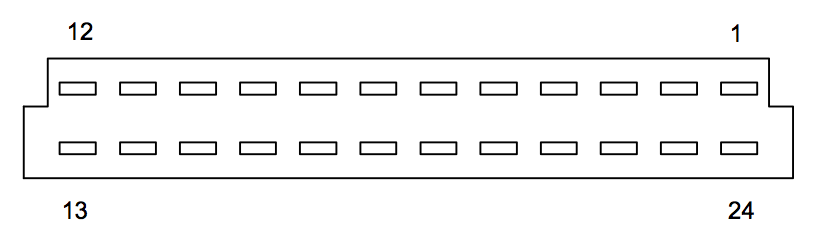
Figure F-1: Xbox audio-video connector, as viewed while looking at the Xbox back panel from the outside.
| Pin | Signal Name | I/O | Comment |
|---|---|---|---|
| 1 | Right Audio | Out | Audio out, right channel |
| 2 | GND | Power | |
| 3 | SPDIF | Out | Sony/Philips Digital Interface (S/PDIF) audio output |
| 4 | VSYNC | Out | Vertical Sync (VGA output mode) |
| 5 | GND | Power | |
| 6 | GND | Power | |
| 7 | GND | Power | |
| 8 | GND | Power | |
| 9 | Pb / B | Out | Pb for HDTV mode, Blue for RGB mode |
| 10 | GND | Power | |
| 11 | Y/G | Out | Y in SDTV and HDTV modes, Green in RGB mode |
| 12 | GND | Power | Has longer pins for hot-insertion |
| 13 | CVIDEO | Out | Composite video out. |
| 14 | GND | Power | |
| 15 | C / Pr / R | Out | C in SDTV, Pr in HDTV, Red in RGB mode |
| 16 | GND | Power | |
| 17 | STATUS | Out | SCART (Syndicat des Constructeurs d'Appareils Radio Récepteurs et Téléviseurs) status pin |
| 18 | MODE3 | In | Video output mode select pin 3 |
| 19 | MODE2 | In | Video output mode select pin 2 |
| 20 | MODE1 | In | Video output mode select pin 1 |
| 21 | HSYNC | Out | Horizontal Sync (VGA output mode) |
| 22 | GND | Power | Left channel audio cable shield |
| 23 | Left Audio | Out | Audio out, left channel |
| 24 | +5V | Power | +5V power, has longer pins for hot-insertion |
Table F-3: Video connector pinouts.
The pin numbering used by Table F-3 for the Xbox video connector is illustrated in Figure F-1. Both the Xboxhacker-derived pinout and the ucon64-derived pinouts disagree in terms of their numbering scheme, so I chose a number scheme that is somewhere in between the two. Interestingly, pin 24 in Figure F-1 is mapped to a square pad on the Xbox video connector, indicating that the numbering scheme I chose to give the connector here is not consistent with the manufacturer’s numbering scheme (square pads typically indicate pin 1, while round pads indicate all other pins). This should not effect the correctness of the table, as pin numbering schemes are arbitrary and only need to be consistent with the pin definition table.
USB Connector Pinout
The Xbox uses a USB derivative for the game controller ports. There are four game controller ports on the front of the Xbox, and all of them have an identical pinout, as shown in Figure F-2.
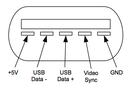
Figure F-2: Game controller pinout, as viewed from outside the Xbox case looking at the connector.
The “video sync” signal is a 3.3V CMOS or TTL-compatible signal. It is a basic 15.734 kHz positive polarity pulse train synchronized to the horizontal line time of the composite video output, with a single longer pulse at the beginning of every video field. This signal enables peripherals that are pointed at the TV screen, such as a light pen or a light gun for shooting games, to derive position information.
The game controllers are connected to the Xbox via an intermediate breakaway connector. The purpose of this break-away connector is to prevent console damage (particularly hard drive damage) by dragging or jerking in the event that a cord becomes entangled around a user’s foot. The pinout of this break-away connector is depicted in Figure F-3.
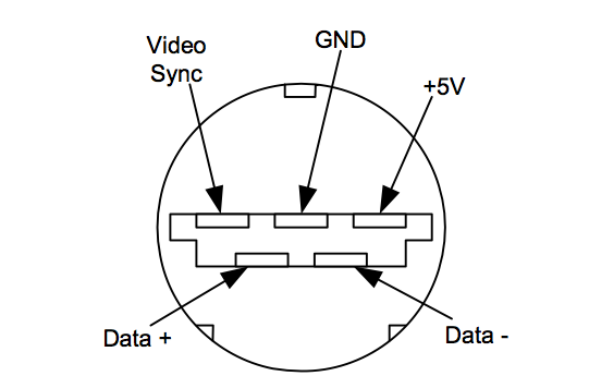
Figure F-3: Game controller break-away pinout, as viewed looking head-on into the connector closer to the Xbox.
The Xbox game controller features two expansion slots for memory cards, microphones and other peripherals. These slots also provide a USB-compliant interface. The game controller contains a USB hub (an Atmel AT43USB401 hub chip) that repeats the incoming USB signal to the expansion slots. The pinout of the expansion connector is illustrated in Figure F-4.
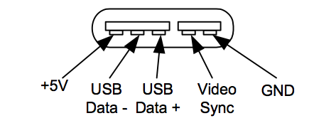
Figure F-4: Game controller expansion slot pinout, as viewed looking into the game controller slot with the buttons facing up.
Ethernet Connector Pinout
The Ethernet port on the Xbox is a standard 10/100 base-TX twisted pair RJ-45 connector. The pinouts and colors of Table F-4 are based on the EIA/TIA 568B standard. Figure F-5 illustrates the pin numbering of the connector.
| Pin | Description | Wire Color |
|---|---|---|
| 1 | Transmit + | Orange stripe |
| 2 | Transmit - | Orange |
| 3 | Receive + | Green stripe |
| 4 | Not connected | Blue |
| 5 | Not connected | Blue stripe |
| 6 | Receive - | Green |
| 7 | Not connected | Brown stripe |
| 8 | Not connected | Brown |
Table F-4: Ethernet 10/100 RJ-45 pinout.
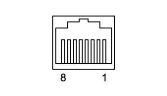
Figure F-5: Pinout of the Xbox ethernet connector, seen looking from the outside toward the back panel of the Xbox.
ATA Connector Pinout
The Xbox uses the standard Advanced Technology Attachment (ATA) bus to communicate with its hard drive and DVD drive. The ATA bus is popularly (but technically improperly) referred to as the IDE (Integrated Drive Electronics) bus. Most drives today qualify as IDE-style drives; for example, SCSI drives also feature integrated drive electronics. However, years of (mis-) use have made the term IDE synonymous with the ATA bus.
Table F-5 gives the pinout of the ATA connector, as viewed on the Xbox motherboard looking down on the connector with the back of the Xbox toward the viewer (the connector should be on the right hand side). Note how the pin numbering zig-zags with all the odd pins on one side and the even pins on the other.
| Pin | Name | Comment | Pin | Name | Comment | |
|---|---|---|---|---|---|---|
| 1 | Reset | 2 | Ground | |||
| 3 | Data 7 | 4 | Data 8 | |||
| 5 | Data 6 | 6 | Data 9 | |||
| 7 | Data 5 | 8 | Data 10 | |||
| 9 | Data 4 | 10 | Data 11 | |||
| 11 | Data 3 | 12 | Data 12 | |||
| 13 | Data 2 | 14 | Data 13 | |||
| 15 | Data 1 | 16 | Data 14 | |||
| 17 | Data 0 | 18 | Data 15 | |||
| 19 | Ground | 20 | Key | Blank pin for polarizing | ||
| 21 | DMARQ | DMA Request | 22 | Ground | ||
| 23 | DIOW- | I/O Write | 24 | Ground | ||
| 25 | DIOR- | I/O Read | 26 | Ground | ||
| 27 | IORDY | I/O Ready | 28 | CSEL | Cable Select | |
| 29 | DMACK- | DMA Acknowledge | 30 | Ground | ||
| 31 | INTRQ | Interrupt Request | 32 | IOCS16- | 16 bit I/O | |
| 33 | DA1 | Device Address Bit 1 | 34 | PDIAG- | Passed Diagnostics | |
| 35 | DA0 | Device Address Bit 0 | 36 | DA2 | Device Address Bit 2 | |
| 37 | CS0- | Chip Select 0 | 38 | CS1- | Chip Select 1 | |
| 39 | DASP- | Dev. Active/Slave Present | 40 | Ground |
Table F-5: ATA connector pinout.
DVD-ROM Power Connector
The Xbox uses a proprietary DVD-ROM power connector. This connector not only brings power, but it also carries a few control and status signals. These signals convey information about the state of the drive and the drive tray. The pinouts given here are from the Xboxhacker BBS, and the original post by Ken Gasper that this pinout is based on can be found at http://www.xboxhacker.net/forums/index.php?act=ST&f=5&t=1025&s=0755f2b600975b776552f93d0730e4b1
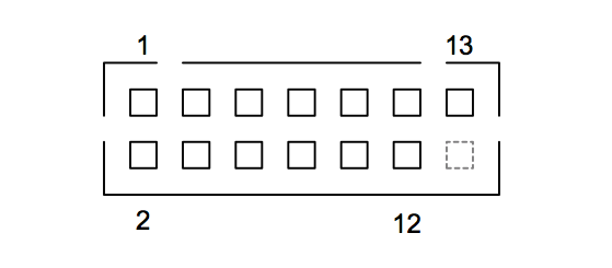
Figure F-6: DVD-ROM power connector pin numbering, as viewed looking down at the Xbox motherboard.
The connector pin numbering, as viewed looking down at the Xbox motherboard, can be found in Figure F-6, and the pinout in Table F-6.
| Pin | Name | Comment | Pin | Name | Comment |
|---|---|---|---|---|---|
| 1 | 12VDC | +12 Volts power | 2 | 5VDC | +5 Volts power |
| 3 | GND | Current return, reference | 4 | EJECT- | Active low tray eject |
| 5 | TS0 | Traystate status 0 | 6 | TS1 | Traystate status 1 |
| 7 | TS2 | Traystate status 2 | 8 | ACTIVITY- | Disk seek/data transfer |
| 9 | 12VDC | +12 Volts power | 10 | 5VDC | +5 Volts power |
| 11 | GND | Current return, reference | 12 | GND | Current return, reference |
| 13 | Key | Not connected | Blank for polarizing |
Table F-6: DVD power connector pinout (viewed on motherboard).
LPC Connector
The Xbox features a debug and test port based on the LPC (Low Pin Count) bus. This bus was originally defined by Intel for use with Southbridge chipsets to reduce pin count, thus saving on cost, while maintaining support for legacy PC I/O functions. These legacy I/O functions used to sit on the nearly extinct ISA bus, and they include the keyboard, mouse, serial port, paral el port, and boot ROM. Intel’s specification for the LPC bus can be found at http://www.intel.com/design/chipsets/industry/25128901.pdf.
The LPC debug connector is particularly significant because it can be used to supply an alternate ROM image to the Xbox in case the built-in ROM is absent or corrupted in a fashion that makes the ROM seem absent or blank. This feature can be and has been used to make an easy to install alternate boot ROM for the Xbox.
The pinout for the Xbox LPC debug connector seems to be based on the Installable LPC Debug Module Design Guide by Intel, http://www.intel.com/technology/easeofuse/LPC_mod_spec72.pdf, with some minor modifications as noted in Table F-7. In particular, the function of pin 16 is unclear, as its companion pin 15 was re-assigned to be a power pin on the Xbox motherboard. The allocation of pin 15 as a power pin is deduced by the fat trace and nearby decoupling capacitor allocated to the pin. If pin 15 were intended for use as a permanently high SPDA1 signal, then a narrower trace without the power conditioning would have been used.
| Pin | Name | Comment | Pin | Name | Comment |
|---|---|---|---|---|---|
| 1 | LCLK | 33 MHz clock | 2 | VSS | Current return |
| 3 | LFRAME# | Start, end of LPC transactions | 4 | KEYWAY | Blank for polarizing |
| 5 | LRST# | LPC Reset | 6 | VCC5 | +5V power |
| 7 | LAD3# | Muxed Address/Data | 8 | LAD2# | Muxed Address/Data |
| 9 | VCC3 | +3.3V power | 10 | LAD1# | Muxed Address/Data |
| 11 | LAD0# | Muxed Address/Data | 12 | VSS | Current return |
| 13 | SCL | I2C serial clock | 14 | SDA | I2C serial data |
| 15 | VCC3 | +3.3V power (was SPDA1 in Intel spec.) | 16 | SPDA0 | Address select for serial EEPROM device (?). |
Table F-7: LPC connector pinout (as viewed on motherboard).
Fan Connector
The fan connector in the Xbox is a three-pin header, where pins 1 and 3 are connected to a temperature-regulating pulse-width-modulation (PWM) fan speed controller, and pin 2 is connected to the +12 volt power supply.
Front Panel Connector
The Xbox’s front panel functions, namely the flashing LED, power switch and eject switch, are connected to the Xbox motherboard through the front panel connector. The pinout of this connector is given in Table F-8. The pinout reflects the pin numbering of the connector on the Xbox motherboard, as seen looking at the connector from above.
| Pin | Comment | Pin | Comment |
|---|---|---|---|
| 1 | Ground | 2 | Power switch |
| 3 | Ground | 4 | Eject switch |
| 5 | Green LED | 6 | Red LED |
| 7 | Red LED | 8 | Green LED |
| 9 | Not connected but wired | 10 | No pin (polarization) |
Table F-8: Front panel connector (as viewed on motherboard).


