This chapter will tell you the basics of what you need to know to start using the GPIO interface on your RP3 to connect it to the outside world via LEDs, sensors, motors, and more. We will review the different pin numbering schemes, look at a table that discusses the purpose of each pin, and give a few examples of how to address the pins.
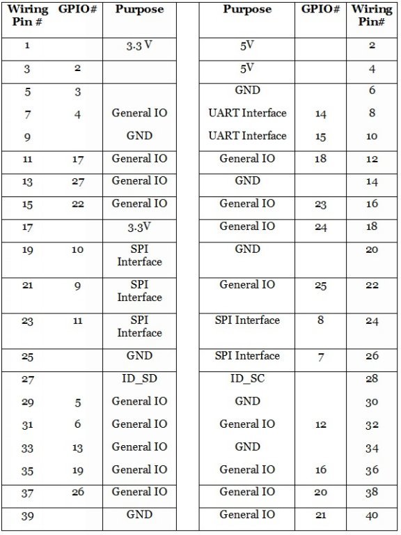
GPIO stands for General Purpose Input Output, and the RP3 has 40 GPIO pins. When you purchased your RP3, you should have also received a card showing the pin numbering scheme and what they the pins are for. In case you have misplaced it, the table below shows what purpose each pin serves.
Before you jump in to using the chart, notice that the pins are not listed in numerical order. The odd numbered pins are listed on the left-hand side, while the even numbered pins are listed on the right-hand side.

Note that wiring pins 1 and 17 provide 3.3V, whereas wiring pins 2 and 4 provide 5V output.
Wiring pins 9, 25, and 39 provide a ground for the odd numbered pins, while wiring pins 6, 20, 30, and 34 provide ground for even numbered pins.
You can access pins that have a GPIO# for reading or writing through the GPIO libraries in Python and Mathematica (and other language compatible with the RP3).
From the computer’s viewpoint, GPIO pins can have one of two values: 1 (high, true, or on) and 0 (low, false, or off). If you want to run current through a pin, you would set it to 1 (high or true). If you want to turn off the current running through a pin, you would set it to 0 (low or false).
You can read the status of a pin, which means to determine if it is set to 1 or 0. Writing to a pin means to change its status from 1 to 0 or from 0 to 1.
Mathematica allows you to read and write to a limited subset of GPIO pins. These are as follows: 4, 7, 8, 9, 10, 11, 14, 15, 17, 18, 22, 23, 24, 25, 28, 29, 30.
Online Resources:
Comprehensive Pin Layout Guide:
Mathematica GPIO:
Python GPIO:

