ARDUINO PROGRAMMING
Step-By-Step Guide To Mastering Arduino Hardware And Software
©Copyright 2017 by Mark Torvalds - All rights reserved.If you would like to share this book with another person, please purchase
an additional copy for each recipient. Thank you for respecting the hard
work of this author. Otherwise, the transmission, duplication or
reproduction of any of the following work including specific information
will be considered an illegal act irrespective of if it is done electronically or
in print. This extends to creating a secondary or tertiary copy of the work or
a recorded copy and is only allowed with express written consent from the Publisher. All additional right reserved.
TABLE OF CONTENTS
.................................................................................................. 13
Questions...................................................................................20
Questions...................................................................................34
Steps....................................................................................... 36
Steps....................................................................................... 36
Questions...................................................................................55
Steps ...................................................................................... 61
Questions...................................................................................76
Questions...................................................................................92
Intro............................................................................................ 94
Questions.................................................................................101
Questions.................................................................................134
Chapter 1
Introduction to Arduino
What you will learn in this chapter
Introduction to Embedded Systems
What is an Arduino?
Why using Arduino?
Arduino Boards
What you will need for this chapter
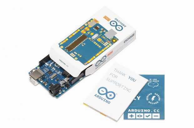
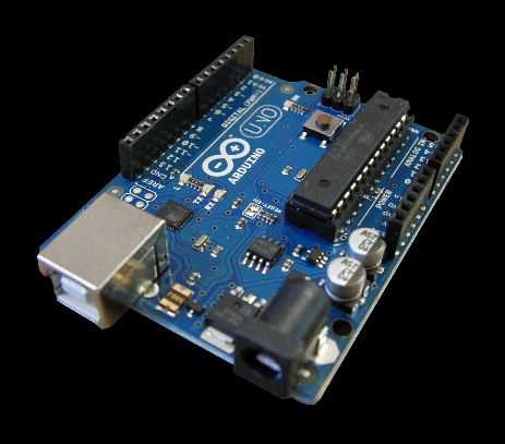
An Arduino UNO Board
Introduction to Embedded Systems
An embedded system is a computer system (Hardware and Software) that designed to do special purpose and usually has no graphical user interface. It can be a microprocessor or a microcontroller based which is the heart of the system the difference between microcontroller and microprocessor is that the microcontroller contain a microprocessor and also peripherals such as flash, RAM…etc. but on the other hand the microprocessor only implements the central processing unit (CPU).
Figure 1.1 description of the microcontroller
 Examples of embedded systems
 ● Embedded systems are widely used in many devices and Applications like:
Automotive Systems
 Figure 1.2 examples of automotive systems
Consumer Electronics
Figure 1.3 examples of consumer electronics
- Digital and Analog Televisions
- Set Top Boxes (DVDS, VCRs, Cable Boxes, etc.)
- Personal Data Assistants (PDAs)
- Cameras
- Global Positioning System (GPS)
Figure 1.4 examples of networking devices
- Routers
- Switches
- Gateways & Hubs
What is an Arduino?
After overviewing the concepts of embedded systems and microcontrollers now it’s time to know exactly what an Arduino is.
Arduino is an open source microcontroller platform and open source here means that you can get the internal designs and the schematics of Arduino and also make derivatives of Arduino boards or entirely new products powered by Arduino technology.
Figure 1.5 schematic of Arduino UNO Rev3
● Arduino has many advantages that make it very popular for makers, hobbyists and even engineers such as:
● Easy to use: you can just program it using USB cable and don’t care about the burner like other microcontrollers.
● Large and supporting community: there are huge supporting communities that can help you to develop any project.
● Arduino Libraries: You can use a lot of libraries in Arduino environment and save your time in writing the codes.
● Arduino Language: It’s so easy to learn the Arduino programming language which developed by the Italian team in 2005. The language is derived from the C programming language and the processing programming language.
Arduino BoardsFigure 1.6 Arduino Boards
The differences between Arduino boards are: ● The number of Input and output pins.
● The type of microprocessor on the board. ● The number of built in parts on the board.
General overview of Arduino UNO
1. Microcontroller: This is the heart of the Arduino Board. Arduino UNO and most boards contain an Atmel microcontroller unit (MCU), use an AVR microcontroller. Arduino UNO here uses an ATMega 328p.This microcontroller is responsible for processing all compiled and the execution of all commands .The Arduino programming language make it so easy to access all the peripherals like Analog to Digital converter (ADCs) , general purpose input / output pins (GPIO).also it contains 16MHz Crystal oscillator.
2. USB Port: used to connect the Arduino to the computer and provide the 5v power to turn on the board.3. DC power jack: when you’re ready to untether your project from the computer, you have other power options like the DC power jack.
4. Power pins: The Arduino has two main regulator:
- 5v for digital input / output.
- 3.3v for used when you connect shields and external circuitry. And also two pins for the ground.
5. Digital Input / Output pins : the most part that we will care about during your projects is the general – purpose input / output pins. We will use it via the programs. They can serve as an input or output and also they have other special function like Pulse width modulation (PWM).
6. Analog Pins: the ADCs pins act as analog inputs to measure voltage between 0v and 5v.7. Reset Button: is used to reload the program on the Arduino board.
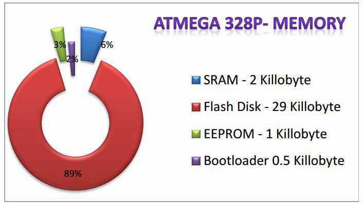
 Memory Types on ATMEGA 328P (the heart of Arduino UNO)
● SRAM: The memory that used to store the variables temporarily.
.
● Flash Disk: It is a storage area that used to store the program which make the microcontroller work.
● EEPROM: Its responsibility is to store some variables permanently like your hard disk in the PC.
● Bootloader: its functionalty to enable programming via USB wih no external hardware.
 Questions
1. What is an embedded system?
2. What is the difference between microprocessor and microcontroller?
3. What is the usage of GPIO pins on the Arduino board? 4. How many memory types and their sizes on Atmega328p?
Chapter 2
Hardware & Tools

What you will learn in this chapter
Prepare and understand your hardware
What you will need for this chapter
An Arduino UNO Board USB Cable
Breadboard LEDs
Resistors Multi meter
Wires
● This is the board that contains the ATMega328P microcontroller. It has 14digital input/output pins including 6 pins can be used as PWM outputs. A 16MHz resonator, a USB connection, a power jack... etc. (for more details you can review chapter 1).
Rev3 features:
●The reset circuit is stronger than the older revisions.
● It includes ATMega 16U2 instead of 8u2.
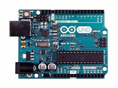 Figure 2.1 Arduino UNO Rev3
A-B USB Cable
● This cable used to connect your Arduino to your computer you can buy any type but I prefer to be as short as possible
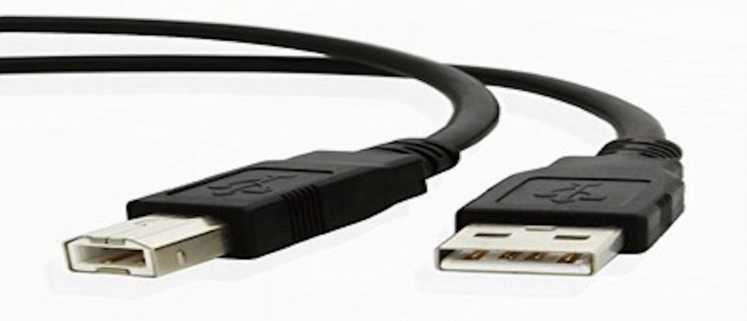
Figure 2.2 A-B USB Cable
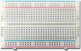
Breadboard
 LEDs
LEDs ● LED stands for light emitting diode. LED something like bulbs also they are available in many types and colors like Red, Green, Yellow, White, orange. They mainly used for debugging purposes.
We will need:- At least 10 LEDs.
Figure 2.4 Different types of LEDs
Multimeter device (optional)
● It’s an electronic device which used to measure voltage, current, resistant, capacitance.
We will need:
- Autoranging multimeter (1) ● Autoranging means that multimeter can detect the measurements rang automatically.
Resistors
● Resistor is an electrical component that used to control the flow of current in the circuit.
We will need:
- 560 ohm resistors (5)
- 10 k ohm resistors (5).
Figure 2.6 Resistor
● Jumper wires used to connect our components with each other on the breadboard.
We will need:
- Male to female wires.
- Male to male wires.
- Female to female wires.
● The Arduino Integrated development environment is the tool that will be used to write and upload the code on our Arduino.
● It uses a very simple programming language which is the Arduino C. Install Arduino IDE on Linux
● You can install the Arduino IDE from the software center in Ubuntu.
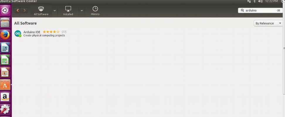
● Write “Arduino” on the search form then click enter / install. ● If you use any other Linux distro you can search for the Arduino IDE on it’s software center.
Install Arduino IDE on Mac / Windows ● Go to https://www.arduino.cc/en/main/software . ● Select the widows / mac installer.
After the installation
● connect the cable to the Arduino board.
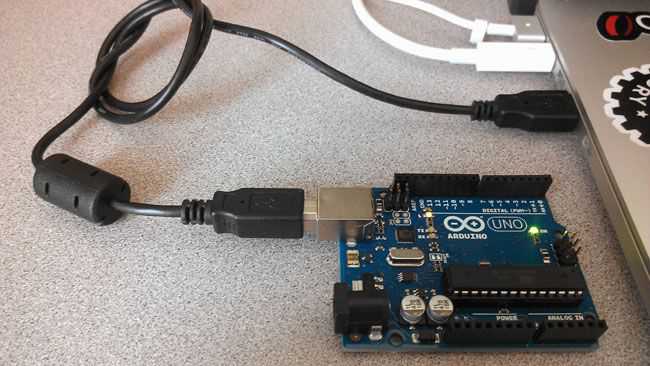
● now open the Arduino IDE.
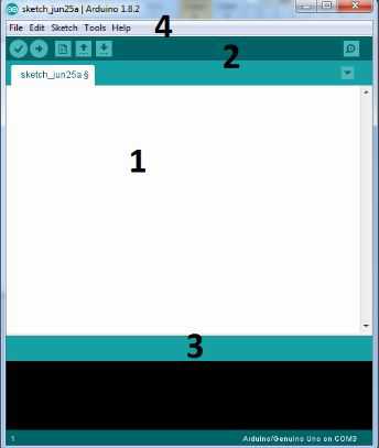
1. The code will be written in this area.
2. Navigation bar to upload , verify, save
3. Console area to show errors and warning.
4. Menu bar.
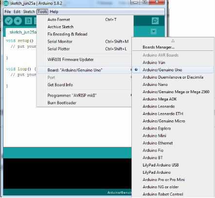
First we will go to tools menu, board then choose Arduino UNO.
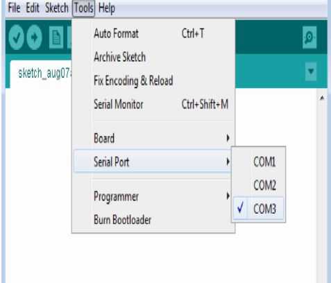
 ● Second we will select Tools, Port then Com (“x”). X is the port number.
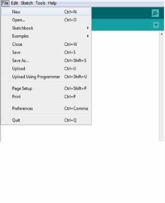
 ● After that you can start writing your first program by selecting file > new
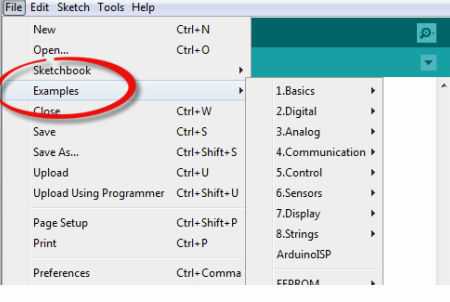
 ● the Arduino IDE provides a lot of completed examples
 Questions
1. What is an Arduino?
2. Define in one statement the following:
- A resistor
- Digital multimeter
- LED
Chapter 3
Getting started with Arduino

What you will learn in this chapter
Write your first Arduino program
Understand the Arduino C language
Electronics basics
What you will need for this chapter
An Arduino UNO Board Wires Computer or any type of PC Breadboard LEDs
Resistors Push Buttons
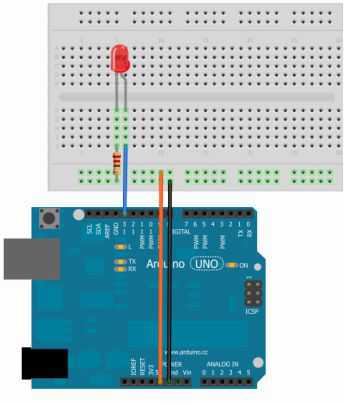
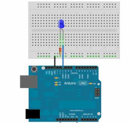
 Steps
Steps● connect the longest leg (+) of the led to pin number 13.
● connect the other leg with the 560 ohm resistor.
● connect the 5v pin and GND pin on the Arduino to the breadboard as shown
First example: LED blinking (Coding)
Steps
● Open the Arduino IDE select File then new.
 ● Write the following code.
 const int LED = 13; void setup ( )
{
pinMode(LED, OUTPUT); }
void loop()
{
digitalWrite(LED, HIGH); delay(1000);
digitalWrite(LED, LOW); delay(1000);
After writing the code now you can press verify for the quick bar on the IDE and wait until “done compiling” then select upload to load the code on the Arduino board.
Congratulations you have done your first program on the ArduinoNow it’s time to explain you the code
● Const int LED = 13;
● We use constants here to make it easy in naming (Input and output) pins
On the microcontroller in the example 1 we declare the constant to control the pin 13 by using name “LED” so we can use the name instead of using the pin 13 for readability.
● Void setup () {PinMode (LED, OUTPUT); To set the pin number 13 to the output mode this has the name “LED”.
There are three steps on to write a program Arduino or any microcontroller
● First of all, declaring the variables that we will use in the program.
● Secondly, it’s really important to understand that all of the digital pins we can set them as an input or output pin, In our example we set the pin 13 as an output.
● PinMode (pin number, state)
- PinMode-> function name.
- Pin number -> the number of the pin we will use.
- State - > to set the pin as an input or output.
● You should write “OUTPUT” or “INPUT” with capital letters.
Setup () {Write you configuration here} , for example If we want to set pin10, pin11, pin 13 as an output
and pin 2 as an input :
Void setup()
{
pinMode(10,OUTPUT); pinMode(11,OUTPUT);
note that every statement must end with semicolon”;”. }
● The final step is to write what the microcontroller should do as in the first example :
Void loop()
{
digitalWrite(LED, HIGH); turn on the led.
delay(1000); wait 1000 millisecond “1 second”.
● keep in mind that the program will be written inside the function void loop () {Write you code here}
● digital write (LED, HIGH)
HIGH = 5 volt
LOW = 0 volt
First we write the pin name and then the voltage.
To tell the microcontroller how much time to wait before the execution of the next instruction, so we can control in time of LED turning off or on
● As we can see in our example:
digitalWrite(LED,HIGH);
delay(1000);
These instructions mean that the microcontroller will apply the 5volt on the output pin which connected to the LED, then it will wait 1000 millisecond.
Note: when we write programs on microcontrollers time should be written in millisecond instead of second “1000 millisecond = 1 second”.● There are two types of comments // this is a one line comment
/* This is
a multiline
comment*/
● we use comment for readability or to describe the code and make it easy to understand
● The Arduino IDE will ignore any comment
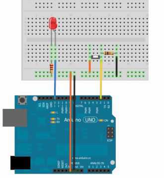
Example 2 (Wiring)
In this example will use a pushbutton to turn on / off the LED
Parts you will need:
- Breadboard
- Push button
- LED
- 10k ohm resistor
- 560 ohm resistor
- Some wires
Steps :
● put the pushbutton on the breadboard.
● Connect one side of the button with the 5v using the wires. ● Connect the other side to the 10k ohm resistor. ● Connect the wire to pin 2 on the Arduino.
/*first step variables declaration and assignment */
const int ledPin = 13;
const int buttonPin = 2;
int val;
{
pinMode(ledPin, OUTPUT); pinMode(buttonPin, INPUT); }
void loop() {
val = digitalRead(buttonPin);
if (val == HIGH)
{
digitalWrite(ledPin, HIGH);
delay(1000);
digitalWrite(ledPin, LOW);
delay(1000);
else {digitalWrite(ledPin, LOW); } }
● Now click on verify button and after the compilation, click the upload button to burn the code on the Arduino board.
● Now it’s time to explain the code
● In the first block
int ledPin = 13;
int buttonPin = 2;
int val = 0;
● We declared a variable called ledPin which assigned to pin13, also we declared another variable called buttunPin which assigned to pin2
And Val variable we will use it to store the input state.● in the second block void setup ( )
{
pinMode(ledPin, OUTPUT);
pinMode(buttonPin, INPUT);
}
● we make the controller work with the pin 13 as an output which assigned before as “ledPin” then we set the pin2 as an input to receive the digital signals
Low or high● In the third block
Val = digitalRead (buttonPin);
In this line, the Arduino will measure the voltage and store the value in the variable Val using the digitalRead () function for example:
- If the button was pressed, so the value will be 5v = HIGH.- Otherwise the value will be 0v = LOW.
If (Val == HIGH)
{
digitalWrite(ledPin, HIGH);
delay(1000);
digitalWrite (ledPin, LOW);
}
else
{
digitalWrite (ledPin, LOW);
}
To compare variables and make the microcontroller do some actions based on the results.
● The Arduino will measure the voltage and store the value in Val. ● If the value is equal to 5v or High, the controller will turn on the led for 1 1 second and turn it off for 1 second
● Unless the value doesn’t equal to 5, so the microcontroller will not turn on the led and will be off.Example 3 (Wiring) led blinking using two push buttons
 Parts you will need:
- Arduino Uno
- Bread board
- Led
- 10 k ohm resistors (2)
- Push buttons (2)
- 560 ohm resistor
- Wires
Example 3 (Coding)
● From the Arduino IDE select file > new and write the following code
/* declaration and assignment of the variables*/ Const int ledPin = 13;
Const int inputPin1 = 2;
Const int inputPin2 = 3;
{
pinMode (ledPin, OUTPUT); pinMode (inputPin1,INPUT); pinMode (inputPin2, INPUT);
}
/* the main program */
Void loop ()
{
{
digitalWrite (ledPin, LOW);
}
else if (digitalRead (inputPin2)== HIGH); {
digitalWrite (ledPin, HIGH); }
}
Chapter 3 Review
Void setup () This function used to set the pins directions as an input or output.
Void loop () in this function body you will write your main program.
example: const int led = 13; statement to define a constant
pinMode(pin number, state); to define the pin number and its direction
example: pinMode(11,INPUT);
digitalWrite(pin number, state) to determine the voltage on the pin example: digitalWrite(13, OUTPUT);
digitalRead(pin number) To read the voltage from the pin example: digitalRead(4);
delay(time) this function used to determine how much time should the Arduino wait
if (the condition) {what to do} else if (another condition) {what to do }
else(last condition) {what to do }
Data Type Integer
example
int led = 13; Float
Character Long
float sensor = 12.5;
char name = ‘a’; Long variable = 99999.9;
55;
Value (range) From -32768 to 32768
With decimal
numbers
character/text From
-2,147,483,648 to 2,147,483,648 from 0 to 255
1. Write code to blink a led 30 times in 1 min
2. Write code to blink two leds in reverse way
3. Design the circuit of the second example using any tool like fritzing
4. How many bits in one byte?
5. Extend the code and the circuit of the second example using push buttons
Chapter 4
Inputs, Outputs and Sensors
What you will learn in this chapter Introduction to signals
Work with sensors
Understand PWM
What you will need for this chapter Arduino UNO Board
Sensors
Multimeter Resistors
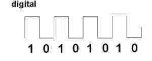
● Digital signal:
A digital signal refers to electrical signal converted into bits (0s / 1s).
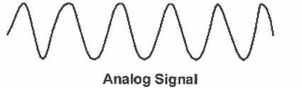
● Analog signal:
Unlike digital signal, an analog signal is any continuous signal for which the time varying feature of the signal is a representation of some other time varying quantity.
Why analog signals are important?
Analog inputs like the voltage of some sensor as a result of changing of some factor, for example
 53
53And we can measure the voltage on this resistor using the multimeter
● We can use this phenomenon to measure any other environmental factor using proper sensors that convert the factor into analog signals such as light, temperature , humidity, power...etc.
● on The Arduino UNO (ATMega 328p) there are 6 input pins for the analog signals it start from A0 to A5, and it can measure voltage with 4.8 millivolt and that means it’s very accurate to measure a lot of applications.
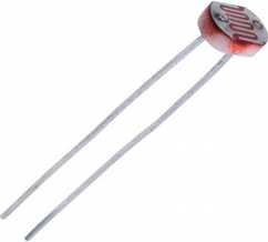
● In this chapter we will work with analog sensors like the photo
resistor, the temperature sensor as TMP35 or LM35 actually it’s a simple transistor changes it’s the voltage by the changing of the temperature.
How sensors generate the analog signals?
Let’s take the temperature sensor as an example; the temperature sensor contains on a very sensitive transistor which made from silicon as we know the silicon is highly affected by the temperature
The temperature sensor has the following
1. Input Vin (2.2v to 5.5v).
2. Signal leg Vout to get the measurement.
3. The ground leg GND to connect it with any ground point.
Components you will need for this example ● Multimeter
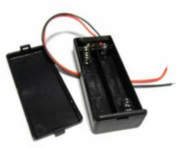
● AAA 1.5 Volt battery (2)
● Temperature sensor (TMP35 or TMP35 or LM35)
● Bring the two AAA Battery and put them together in the battery holder and you will get 3 volt.

● Connect the red wire with of the battery holder to the temperature Vin leg
● Connect the black wire of the battery holder to the temperature sensor GND leg.● put your multimeter the voltage mode as shown
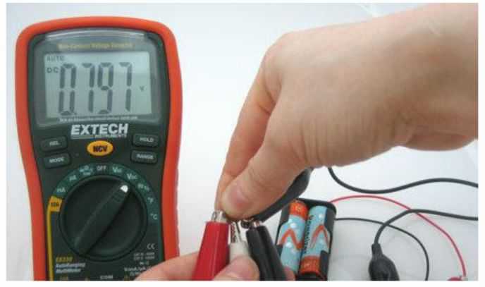
● connect the GND Leg to the black probe, and connect the red probe to the Vout leg as shown.
● note the reading of the voltage on the multimeter it will be 0.76 volt● now put your hand on the sensor (this movement will raise the temperature and as we know that the human temperature is 37 Celsius) and the note the reading of the multimeter
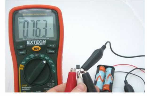
You will find that the reading become higher
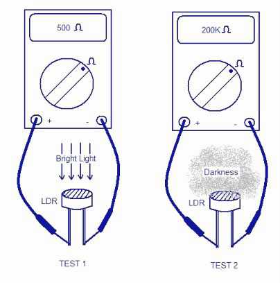
● Any sensor work in the same manner of the temperature sensor, it behaves depending on the environmental factor and changes its internal resistor, so as a result changes the output voltage which generate an analog senor can be measured.
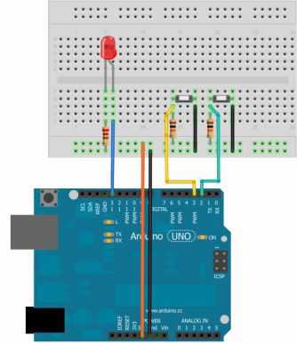
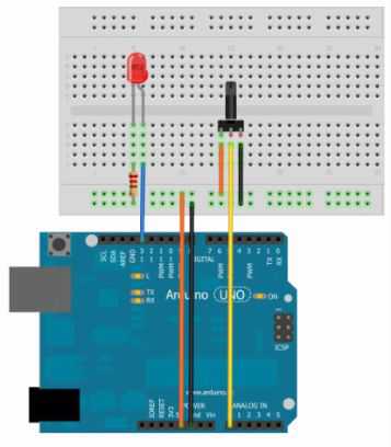
Example 4: control light amount using potentiometer (wiring)
● In this example we will use a potentiometer to get a changeable
voltage (analog input) and we will turn on / off the LED depending on
the value of the analog input.
Example components
● Arduino UNO Board
● Breadboard
● LED
● 560 ohm resistor
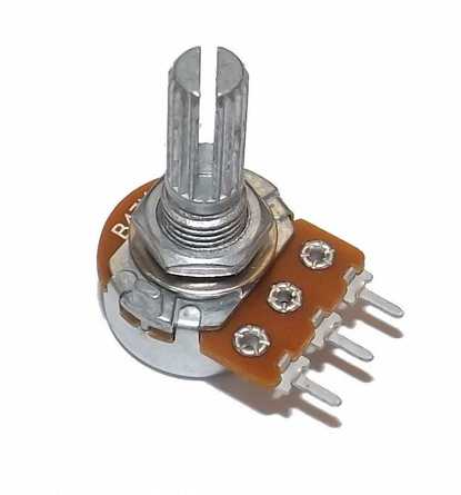
● 10 k ohm potentiometer
● Wires
Connect the components as shown
Example 4: control light amount using potentiometer (Coding)
//create new file form the Arduino IDE and write the following code
const int sensorPin = A0;
const int LedPin = 13;
int sensorValue;
{
PinMode (LedPin, OUTPUT); }
void loop()
{
sensorValue = analogRead(sensorPin);
digitalWrite(LedPin, HIGH);
delay(sensorValue);
digitalWrite(LedPin, LOW);
delay(sensorValue);
}
In this example we use on of the most important functions in the Arduino language analogRead(pin number) this function reads the voltage as an analog signal, the microcontroller can measure voltage from 4.8 millivolt to 5 volt, and also it converts these values to digital values from 0 to 1024 this conversion called Analog to digital converting (ADC).
For example
If the input voltage to the A0 equals to the following values: 4.8millivolt = 1 in digital 49millivolt = 10 in digital 480millivot = 100 in digital
1volt = 208.33 in digital 2volt = 416.66 in digital 5volt = 1024 in digital
sensorValue = analogRead(sensorPin);● in this statement the microcontroller will store value of the sensor reading in the sensor value variable and, then the microcontroller will turn on / off the LED for period of time equals to this variable (sensorValue).
● In this example we have used a variable resistor, so we could change the its value of the resistance.
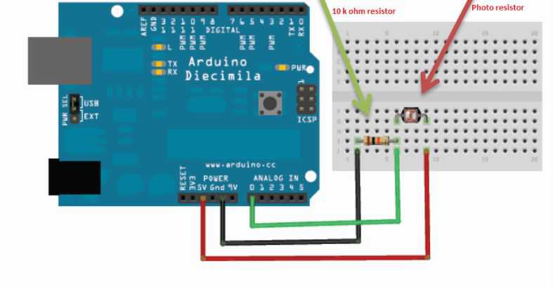
 Example 5 photo resistor as light sensor (Components) ● Arduino UNO Board
 ● Breadboard
● LED
● 560 ohm resistor
● Photo resistor
● wires
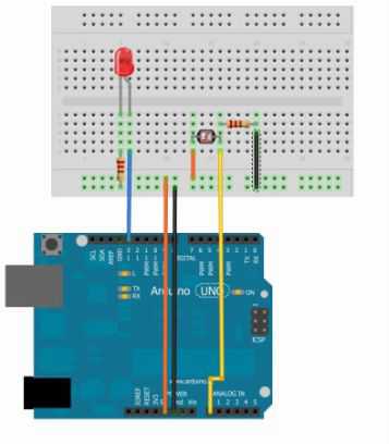 ● Connect the components as shown
 Example 5 photo resistor as light sensor (Coding) // select new file from the Arduino IDE
const int lightPin = A0;
const int ledPin = 9;
int lightLevel;
{
pinMode(ledPin, OUTPUT);
}
void loop () {
lightLevel = analogRead(lightPin); lightLevel = map(lightLevel, 0, 900, 0 , 255)
lightLevel = constrain(lightLevel, 0, 255); analogWrite(ledPin, lightLevel);
}
● Now you can upload this code on you Arduino board and look what will happen to the LED after focusing the light on the photo resistor and then put you hand on the photo resistor and look what will happen to the LED.
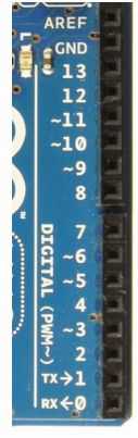
● analogWrite(pin number, value);This function generate an analog output, and this can function can be applied to all of pins with pules width modulation (PWM) . They are pin3, pin5, pin6, pin9, pin10, pin11 (any pin with ~ sign)
What is the pulse width modulation?
The pulse width modulation is a technique for getting analog results with digital means. Digital control is used to create a square wave, a signal switched between on and off. This on-off pattern can simulate voltages in time that the signal spends off. The duration of “on time” is called the pulse width. To get varying analog values, you change or modulate that pulse width. If you repeat this on-off pattern fast enough with an LED.
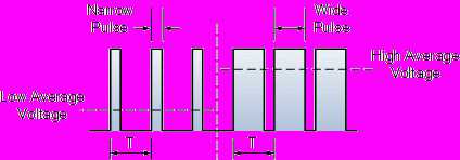 How we can use it?
A lot of electric components are dealing with different voltage values
For example when you apply 3 volts to the LED you will get very small amount of light, and if you raise the voltage to 4 volts you find out that the light will be more brighter and so on ..
And if you use a motor for example when you increase the voltage the speed of the motor will be faster.Example 6: LED with PWM (wiring)
 ● Connect the components as shown
Example 6: LED with PWM (coding)
// open the Arduino IDE and select new file then write the fowling code
const int ledPin = 11;
int i = 0;
void setup( )
{
pinMode(ledPin, OUTPUT);
}
void loop()
{
for (i = 0; i < 255; i++) // LED will be lighter {
analogWrite(ledPin, i);
delay(10);
}
for (i = 255; i > 0; i--) //LED will be darker {
analogWrite(ledPin, i);
delay(10);
}
}
● in the previous example we used new statement which is the for loop statement. You can use the for loop if you want to run the same code over and over again, each time with a different value.
I = 0 the initial value
I < 255 to set your condition
I++ is the iterator in this example will add 1
I++ I = I +1
1. Describe the difference between the digital and the analog signals?
2. What is the pulse width modulation?
3. Design a circuit to turn on /off 5 LEDs in sequence order? 4. Write the code for the example 3?
Chapter 5
Computer interfacing with Arduino
 What you will learn in this chapter
 How to interface your Arduino with your computer
What you will need for this chapter
An Arduino UNO Board
Breadboard
Sensors
Wires
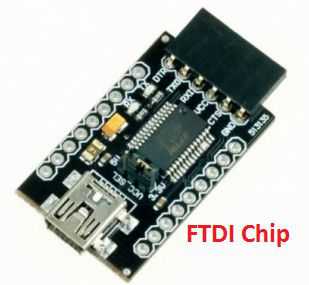
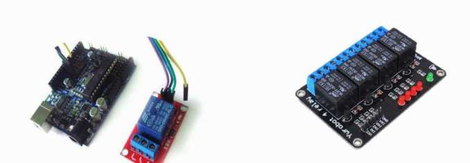
● All of the Arduino boards have the capability of sending and receiving with computer directly through the USB port expect (mini , lilypad ) Arduino boards , but you can also interface these boards with the computer using FTDI Interface, it’s small chip used to exchange the data between the Arduino or any microcontroller and the computer.
 ● In the last examples we used the Arduino to read some sensors value Like the light, temperature sensors, and show the results on the LED.
● In this chapter the serial interface to send the sensors values to the computer, and we can make the calculations easily.
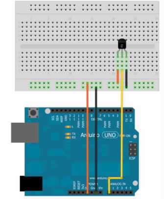
Example7: Temperature sensor with serial interface (Components)
● An Arduino UNO board
● Temperature sensor (TMP 36 or LM35)
● A – B USB cable
Example7: Temperature sensor with serial interface (Wiring)
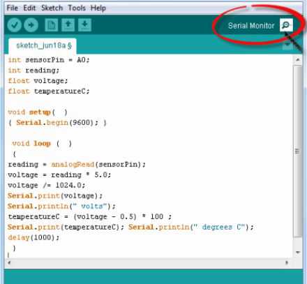
Example7: Temperature sensor with serial interface (Coding)
const int sensorPin = A0;
int reading;
float voltage;
float temperatureC;
void setup( )
{ Serial.begin(9600); }
void loop ( )
{
reading = analogRead(sensorPin);
voltage = reading * 5.0/1024;
Serial.print (voltage);
Serial.println(" volts");
temperatureC = (voltage - 0.5) * 100 ;
Serial.println("Temperature is: ");
Serial.print(temperatureC);
Serial.println(" degrees C");
delay(1000);
}
 ● You will see this menu that show the temperature sensor readings
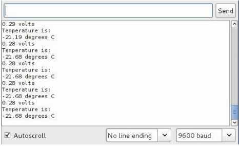 ● Now try to raise the temperature using any heating source. ● You should be aware that this sensor can handle until 150 Celsius.
● (-) this symbol doesn’t mean negative, but it is a temporary programming error.
Example7: Temperature sensor with serial interface (Explanation) Serial.begin (9600);
● We write this statement to start the communication between the Arduino and the computer through the USB port, so we can receive and send from and to the computer
● There are two variables in our code (voltage, TemperatureC) have been defined with float instead of int because the temperature sensor is a very accurate sensor , and the result will be in floating points number not integers .
reading = analogRead(sensorPin);
● This instruction used to record the analog input in A0 Pin
● After the conversion of digital values to voltage we used Serial.print (voltage);
to send this value to the computer and show it on the Arduino IDE ● Serial.print (“voltage”); this instruction used to print the word “voltage ”
after its value● TemperatureC = (voltage – 0.5) *100; this instruction to convert the voltage values to temperature degrees in Celsius, and print the value then the word “Temperature” and “degree C”
Serial.print(TemperatureC);
Serial.println(“degree C”);
● the last line of code is delay (1000); to make the microcontroller wait one second, before sending the voltage and the temperature value to the computer again.
Example 8: showing the strength of the LED Light on the serial monitor (Wiring)
 Example 8: showing the strength of the LED Light on the serial monitor (Coding)
 const int photocellPin = A0;
int photocellReading;
void setup(void)
{ Serial.begin(9600); }
void loop(void)
{
photocellReading = analogRead(photocellPin);
Serial.print("Analog reading = ");
Serial.print(photocellReading);
if (photocellReading < 10) { Serial.println(" - Dark");} else if (photocellReading < 200) { Serial.println(" - Dim");} else if (photocellReading < 500) {Serial.println(" - Light"); } else if (photocellReading < 800) { Serial.println(" - Bright"); } else {Serial.println(" - Very bright"); }
delay(1000);
}
After uploading the code on the Arduino, click on the serial monitor
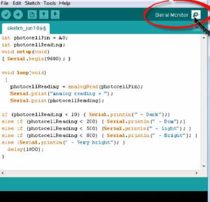
● Now try to do the following
- Focus the light on the photo resistor
- Cover the photo resistor with any transparent piece of clothing
- Cover the photo resistor with your hand and make no light on it ● This is what you will see
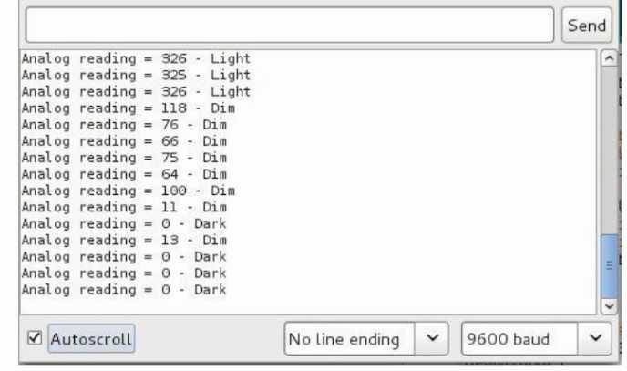
● Dim the amount of the light will be small
● Dark there is no light
● Light there is a moderate amount of light
● Bright light the brightness of the light is very high
● Breadboard
● LED
● 560 ohm resistor
● Wires
● In this example will use the computer to control the LED instead of using a switch, and the Arduino will receive the command using serial monitor through the USB port
Example:9 turn on / off your led using your computer (Wiring)
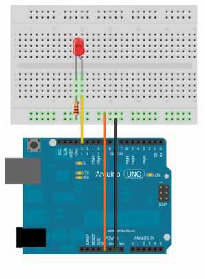
Example: 9 turn on / off your led using your computer (Coding)
int ledPin=13;
int value;
void setup ()
{
Serial.begin(9600);
pinMode(ledPin,OUTPUT);
}
void loop ()
{
value = Serial.read();
if (value == '1') {digitalWrite(ledPin,HIGH);} else if (value == '0') {digitalWrite(ledPin,LOW);} }
After the uploading of the code on the Arduino , click on the serial monitor icon you’ll find a search bar write “1” on it , and click send, then write “0”, and watch what will happen to LED.
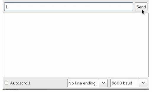
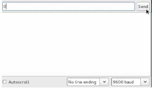
● In this example we have used the Serial.Read(); instruction to read the data that send from the computer to the Arduino though USB , also we added the variable “value” to store the data.
.Then we used if… else if statement
● if value == 1 the microcontroller will turn on the LED
● if value == 0 the microcontroller will turn off the LED
1. How do you can make the Arduino communicate with the computer?
2. What is the FTDI Chip, and how can we use it?
3. Design a circuit to connect the Arduino with temperature sensor and a LED?
4. Write the code for the example 3 and control the LED based on the readings of the temperature sensor?
Chapter 6
The Motors
What you will learn in this chapter
Introduction to motors
Types of the motors
Interfacing the motors with Arduino
What you will need for this chapter
An Arduino UNO Board
Breadboard
Transistors
DC / Servo motor
● The motor is a very important electric component that you will need in a lot of projects because it’s the element that converts electrical energy into mechanical energy
● You can find the motors in a lot of applications such as robot, cd
drives, toys…etc.
● There are mainly two types of motors
- Direct current motors (DC – Servo - Stepper)
- Alternative current motors (1Phase – 3Phase)
Example: 10 using the direct current motor “DC Motor” (Components)
● An Arduino UNO Board
● Breadboard
● DC motor
● 2N2222 or PN2222 Transistor
● 1N4001 Diode or any alternative
● 2.2 k ohm resistor ● Some wires
● USB Cable
● In this example we will use the small size of the direct current motor that usually used in toys, it can work with 3volts to 9volts, and you can easily find this type of motors in the electrical components store or any toys store
Example: 10 using the direct current motor “DC Motor” (Wiring)
 ● After connecting the components with the Arduino UNO Board, you can start writing the following code, and upload it on the Arduino
 int motorPin = 9 ;
int onTime = 2500 ;
int offTime = 1000 ;
void setup ) (
{pinMode(motorPin, OUTPUT); } void loop ) (
{
analogWrite(motorPin,100); delay(onTime);
digitalWrite(motorPin, LOW); delay(offTime);
analogWrite(motorPin,190); delay(onTime);
digitalWrite(motorPin, LOW); delay(offTime);
analogWrite(motorPin,255); delay(onTime);
digitalWrite(motorPin, LOW); delay(offTime);
}
Example: 11 using the direct current motor “Servo Motor” (Components)
● An Arduino UNO Board
● Breadboard
● DC motor
● 2N2222 or PN2222 Transistor
● 1N4001 Diode or any alternative
● 2.2 k ohm resistor
● Some wires
● USB Cable
Example: 11 using the direct current motor “Servo Motor” (Coding)
#include <Servo.h> // additional library for the servo motor
Servo myservo;
int pos = 0;
void setup()
{
myservo.attach(9);
}
void loop()
{
for(pos = 0; pos < 180; pos += 1)
{
myservo.write(pos);
delay(15);
}
for(pos = 180; pos>=1; pos-=1)
{
myservo.write(pos);
delay(15);
}}
● Also you can find the sample of the code in the completed examples from the Arduino IDE
Examples – servo – sweep
Questions
1. Describe the different types of motors?
2. Design a circuit to connect servo motor and Arduino?
3. Extend the example 3 using a LED, and make the following
- If the motor is on turn on the LED
- If the motor is off turn off the LED
4. Using a DC motor and a LED, do the following
- If the speed of the DC motor is the max make the led flashing quickly
- If the speed of the DC motor is a moderate speed make the led flashing in a moderate speed
- If the speed of the DC motor is a low speed make the led flashing in a low speed
Chapter 7
Advanced Inputs and Outputs
What you will learn in this chapter
Learn the Different types of displays
Understand relays
What you will need for this chapter
An Arduino UNO Board
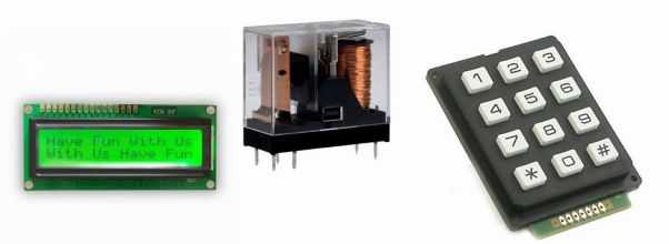
Different types of display (LCD, Keypad…)
● In the last chapters, we used simple inputs and outputs devices with
Arduino such as (switch, LED…)
● In this chapter, I will show how to use the advanced Inputs and outputs like:
● Liquid Crystal Display “LCD”
● The Keypad
● The LED matrix
● The Relays
● Let’s take a look at the liquid crystal display “LCD” this type of display was made from crystal, and we will use the most two popular types which are:
● Character liquid crystal display “LCD”● Graphical liquid crystal display “GLCD”
● The character LCD has the capability of displaying text of characters, numbers or symbols (like the characters we type from the keyboard), you can find different sizes and colors of the character LCDs
Green 16x2 LCD
Blue 16x2 LCD
Grees 20x4 LCD
● as an example, 16x2 means the following:
- Number of the lines is two
- Number of the characters in every line is 16
You can choose from different sizes and colors
● 16x2 LCD with blue light (or any color you prefer) ● Copper pins headers 16 points
● 10 k ohm potentiometer
● Soldering iron
● Soldering wires
● Solder the pin headers with the LCD points using the soldering iron
● Solder the first point using the wire and the soldering iron, and wait for 5 seconds to make sure that the point is not hot for your safety, also don’t try to touch it with your hand
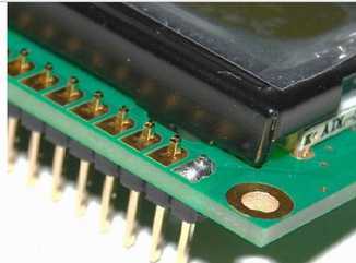 ● Solder the last point to hold the LCD from the both sides
 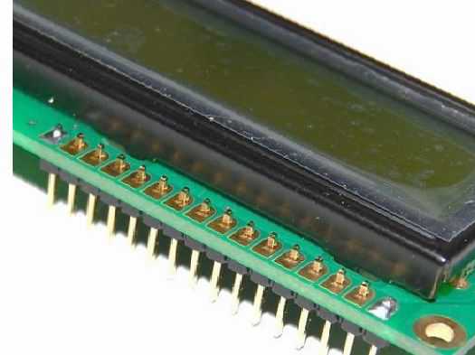 ● repeat all of the procedures again to all 16 pins as shown
● after finishing of the soldering, Now it’s the time to put it on the breadboard
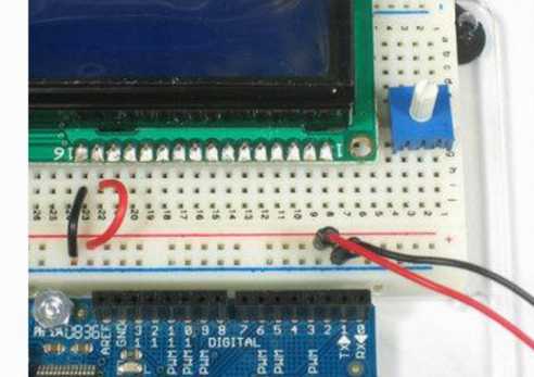
● Connect the Arduino 5v pin with red line pins on the breadboard, And the GND pin with the blue line pins on the breadboard
● Connect the pin number 16 on LCD to the GND line, and the pin number 15 to the Positive line as shown in this picture
● Connect the Arduino with the USB Cable or the battery, and look at the light on the LCD
● The color of display maybe different depend on your LCD color choice, there are also another colors like: Red, white, green, blue
Use the potentiometer to control the brightness of the display
● This is an optional step that you can skip, the goal of using the potentiometer is to control the amount of current inside the LCD, so we can control the light brightness on your display
● connect one of the legs of the potentiometer to the red positive line, and the other leg with the black negative line
● Connect the middle leg of the potentiometer to the third pin on the LCD as shown
● Now connect the pin number 1 to the ground, and pin number 2 to the positive line on the breadboard as shown
● Connect the battery to your board, and rotate the hook of the potentiometer, and watch the difference on the light brightness of your display
● The goal of all previous steps is to connect the LCD to the potentiometer and the battery to control the brightness of the display
 ● In some projects we may use the pin number 5 which is called RW, but in our project we connect it to the ground
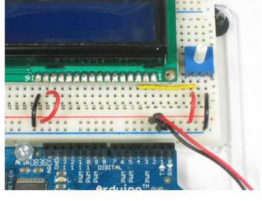
● now connect the pin number 4 on your LCD to the pin number 7 on the Arduino
● After that you can connect the pin number 6 on your LCD to the pin number 8 on the Arduino board as shown
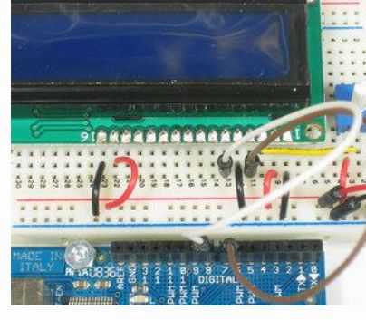 ● Connect he pin number 14 on your LCD to the pin number 12 on your
 Arduino Board
●The final step is to connect the pins number 11, 12, 13 on your LCD to the pins number 10, 10, and 11 in the same order as in the following picture
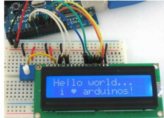
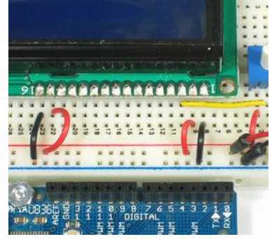
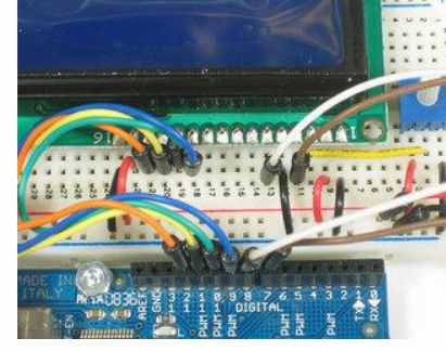 ● This is the final circuit of interfacing the Arduino with the LCD ● Now it’s time to write the code
 ● The Arduino IDE has a lot of completed code examples that you can choose from, and save your time in writing the code
● From the Arduino IDE open
File Examples Liquid Crystal Hello World
● We need to edit the code a little bit, for the first line LiquidCrystal lcd (12, 11, 5, 4, 3, 2);
Do the following
LiquidCrystal lcd (7, 8, 9, 10, 11, 12);
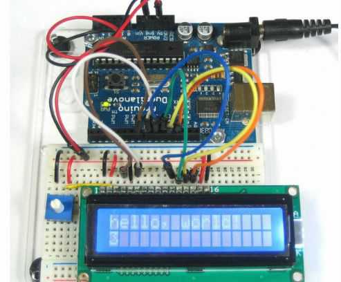
//Example_12_LCD_16x2
#include <LiquidCrystal.h>
LiquidCrystal lcd(7, 8, 9, 10, 11, 12); void setup()
{
lcd.begin(16, 2);
lcd.print("hello, world!");
}
void loop()
{
lcd.setCursor(0, 1);
lcd.print(millis()/1000);}
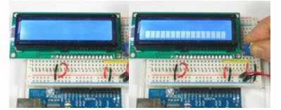
● this is what you will get after wiring and coding
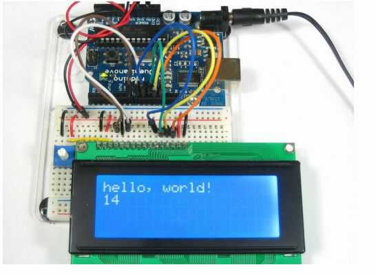
 ● Also you can change the display brightness using the potentiometer
 ● You may choose any type or color from different types of the character LCDs in the market
 for more examples of LCD projects visit
https://www.arduino.cc/en/Tutorial/HelloWorld?
from=Tutorial.LiquidCrystal
Interface the Keypad with the Arduino
We consider the keypad as a very important type of an advanced input device that you can find it easily in a lot of applications such as the telephone, the keyboard, the control panel of the elevator, and so on...
There are many types of keypads, they differ in size and number of characters, in some keypads you can find extra symbols like star (*), Baum symbol (#) or maybe like English characters such as A.D.F
The most popular keypad sizes are 4x4 and 4x3
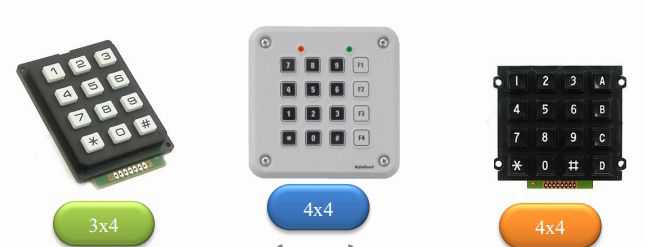 There are some special keypads which are more flexible and thinner that made from materials, and it’s very cheap also
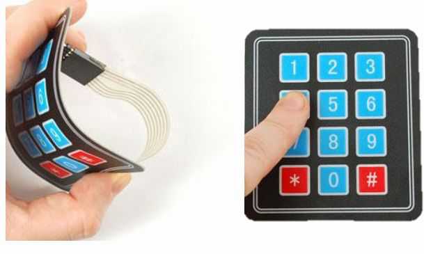
The specifications of 3x4 keypad
weight: 7.5 gram
Keypad dimensions: 70mm x 77mm x 1mm (2.75”x 3” x 0.035”) Length of cable + connector: 85mm
7-pin 0.1” pitch connector
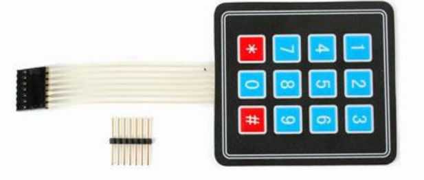 Example11: using the keypad with Arduino (Components) 3x4 keypad
 pin headers (7)
Arduino UNO Board
Breadboard
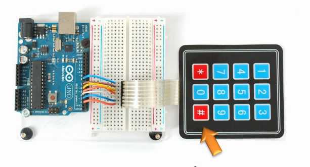 Connect the pins number 2, 3, 4, 5, 6,7and 8 on the Arduino to the pins on the keypad but connect # with pin 2 on the Arduino
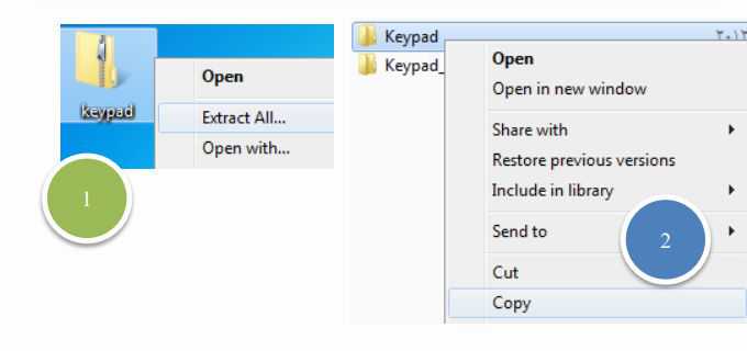
 Before start writing the code for the Arduino, you should firstly download the keypad library from the Arduino website
Because it doesn’t exist in the Arduino IDE
Here is the link that you can download the library
http://playground.arduino.cc/Code/Keypad
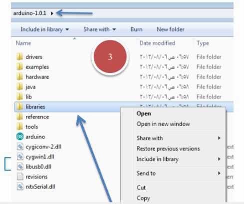
It will be as a zip. Keypad, so the next step will be to extract the file and copy the files and paste it in the libraries folder which is in the Arduino IDE folder in your computer as shown int the following picture
 ● Example11: using the keypad with Arduino (Coding) //Example_13_Keypad_Input
 #include <Keypad.h>
const byte ROWS = 4;
const byte COLS = 3;
char keys[ROWS][COLS] =
{
{'1','2','3'},
{'4','5','6'},
{'7','8','9'},
{'#','0','*'}
};
byte rowPins[ROWS] = {5, 4, 3, 2};
byte colPins[COLS] = {8, 7, 6};
COLS (;
void setup)(
{
Serial.begin)9600(;
}
void loop)(
{
char key = keypad.getKey)(;
if )key != NO_KEY( {مSerial.println)key(;
}
After writing and uploading the code on Arduino, click on the serial monitor icon and watch will happen
Introduction to relays
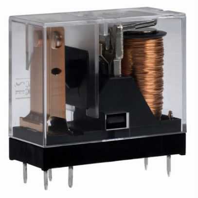 The relay is one of the most component that you will see in a lot of projects specially project with appliances
 What is a relay?
A relay is an Electromechanical device we can imagine a relay
as a switch that we can divide it into two main parts:
- The second part is: a rectangle of iron block, and this is the switch which makes the relay in on or off state
The relay symbol
- The left side is the coil
- The right side is the switch

Let’s take a look at the internal design a relay
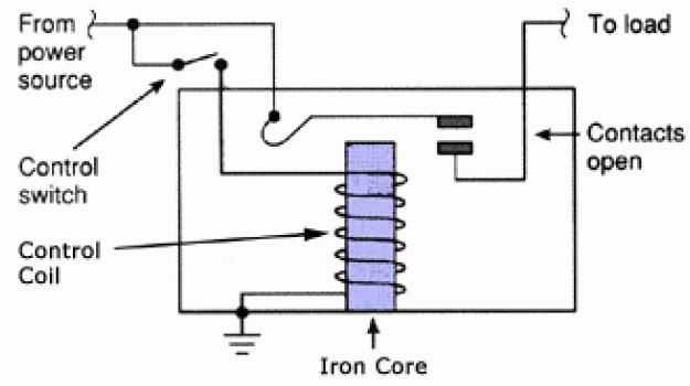
 If you want to understand more about relays go to https://www.sparkfun.com/tutorials/119
Questions
1. What is a relay?
2. With the following parts design an access control system:
- Arduino board
- Keypad 4x4
- Proto Board
- Breadboard
- Servo motor
- Jumper wires
Chapter 8
Arduino shields
 What you will learn in this chapter
 Take a look at different types of Arduino shields
Intro to shields
One of the most important advantage of using Arduino is the
availability of different types of shields that can integrate we the
Arduino
The idea of Arduino shields is something like your PCI cards on your PC motherboard such as the network interface card that makes you access the internet so easy, and the Arduino shields work in the same manner
If you have any experience with microcontrollers, you can imagine the effort of connecting the microcontroller to the internet or a local area network (at this situation you need to build the Ethernet module from scratch) , and it take a lot of time and effort
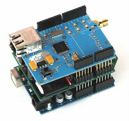
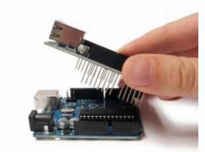
But with Arduino you just need to buy an Ethernet shield,
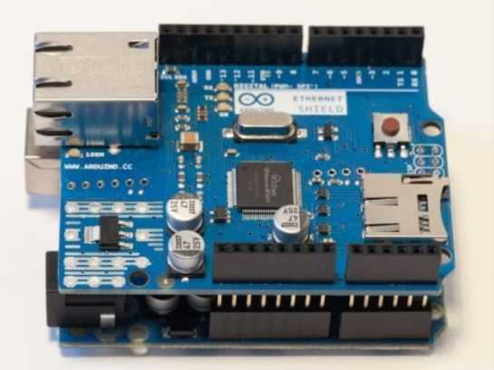
- There are many types of shields like the following examplesArduino Ehternet Shield
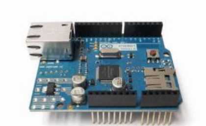
This Arduino Ethernet shield can connect the Arduino with the internet using the cat5 cable, and you can use this shield to control things remotely through the internet
This shield has an option to add SD card that used to store something periodically like the temperature values
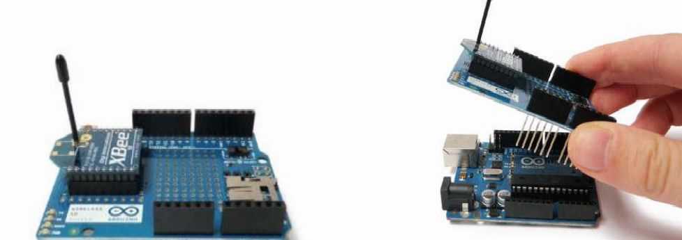
 XBee Shield
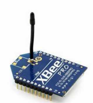
This is the Xbee shield it can do the same functions as the Ethernet functions, but in wireless way, you can connect the Arduino to any wireless network in rang of 100 meters
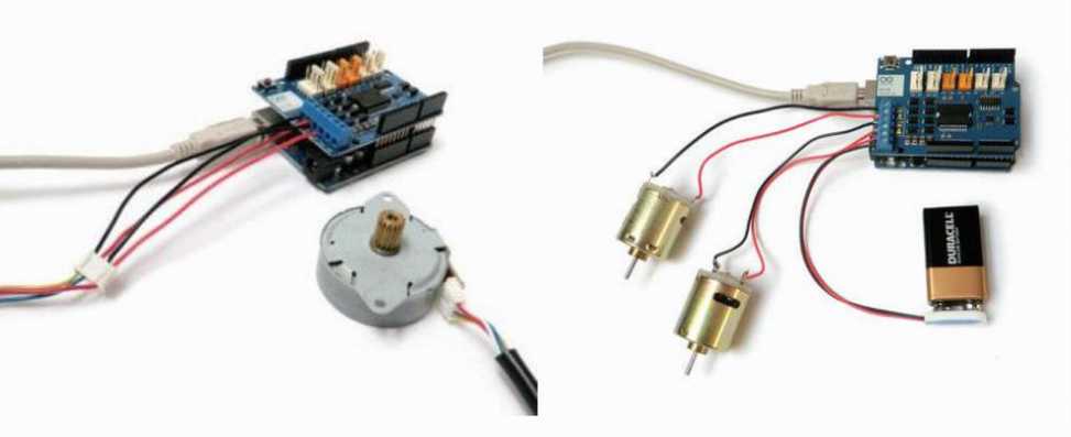
 Arduino Motor Shield
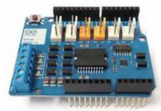
The motor shield is used to connect different types of motors like (DC Motor, Servo Motor, Stepper Motor) , and you can connect 3 motors in the same time
Some versions of the motor shield allow you to connect just two motors in the same timeYou can use this shield in projects that need motors such as The robots and CNC machines
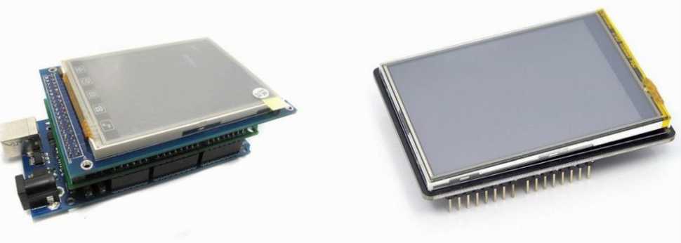
 Arduino Colored Touch Screen
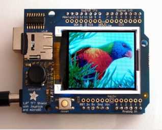 This shield can be used in any interactive project to allow you show some data like photos that the LCD cannot handle it There are different sizes of this kind of the touch screen shield start from 2 inches to 4 inches
 Questions
1. What are the benefits of using Arduino shields?
2. How many motors can we use on the motor shield? 3. Describe the Xbee shield?
Chapter 9
Final Project

What you will learn in this chapter
apply what you learned in one project
What you will need for this chapter
An Arduino UNO Board USB Cable
Breadboard LEDs
Hardware and software requirements
In this part you will need the following components An Arduino UNO board
Arduino Ethernet shield
USB Cable
Before start assembling the Arduino and the Ethernet shield, write down the MAC address of the shield, which is written on the back of the shield.
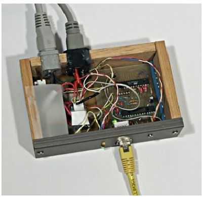
 Hardware configuration
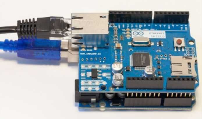
 The hardware configuration for this part is very simple. At this point, you should already have the Ethernet shield which is connected to the Arduino UNO board.
Now plug the Ethernet cable into the Ethernet shield and USB cable to the Arduino board and you computerConnect directly the Ethernet cable to the main router of your home. Usually, you will have a Wi-Fi-router in your home, which you use to enable Wi-Fi connectivity for your computer and other devices in your home network. This router should also have ports, that you could connect your Ethernet cable
The advantages of using this method is that your Ethernet shield will automatically get an IP address, so you can access the internet easily, in case your router is configured for DHCP which is depend on your router you use
In case you don’t have a router, you can just connect the Ethernet cable to your computer, but sharing the internet with your Arduino board will be very complex
Test the connection
Start the Arduino sketch with the following
Download the Ethernet library code from Arduino.com #include <SPI.h>
#include <Ethernet.h>
/*you must define the mac address to test the connection We will test the connect by grabbing a request from any simple web page
*/
/* The web address is store in a char variable, you can check the data types in chapter 3*/
char server[] = “www.example.com”; // write any website
/*the Ethernet shield will get the IP of this website*/
/* let’s create an instance of the Ethernet client*/ EthernetClient client;
// write the following in your setup function
void setup() {
If (Ehternet.begin(mac) ==0) {
Serial.println(“Failed to configure the Ethernet”); Ethernet.begin(mac, ip);
}
Serial.begin(115200);
Serial.print(“IP address: ”);
Serial.println(Ethernet.localIP());
}
Loop()
{
client.printlin(“GET /java/host/test.html HTTP/1.1”); client.println(“Host: www.example.com”);
client.println(“connection: close”);
client.println();
while(client.connect()){
while(client.availabel()){
char c = client.read();
Serial.print(c);
}
If(!client.connected()) {
Serial.println();
Serial.println(“disconnecting”);
Client.stop();
}
}
}
// Include these libraries, you can download it #include <SPI.h>
#include <Ethernet.h>
byte mac[] = = {0x80, 8XA2, 0xDA, 0x0E, 0xFE, 0x40};
// Define the server
char server[] = "www.example.com";
// Set an IP address IPAddress ip(192,168,1,50);
// create an instance EthernetClient client;
void setup() {
// start the serial communications Serial.begin(115200);
// Start the connection
if (Ethernet.begin(mac) == 0) {
Serial.println("Failed to configure the Ethernet ");
Ethernet.begin(mac, ip);
}
// Display the IP address
Serial.print("IP address: "); Serial.println(Ethernet.localIP());
// Give the Ethernet shield a second to initialize delay(1000);
Serial.println("Connecting...");
}
void loop() {
// Connect to servers
if (client.connect(server, 80)) { if (client.connected()) {
Serial.println("connected");
// Make a HTTP request:
client.println("GET /java/host/test.html HTTP/1.1"); client.println("Host: www.example.com"); client.println("Connection: close");
client.println();
}
else {
// If the connect was failed
Serial.println("connection failed");
}
// answer reading
while (client.connected()) { while (client.available()) { char c = client.read(); Serial.print(c);
}
// If the server's disconnected, stop the client: if (!client.connected()) {
Serial.println();
Serial.println("disconnecting.");
client.stop();
}
// Repeat every 3 seconds delay(3000);
}
Now it’s the time to sending the data to the web server In the previous part we made sure that the shield Is working well and connected to your network
In this part we will do the following
First, we will use the temperature and humidity sensor, and install the software components to plot the data in your computer
Second, we will build the code that calculate the measurements and send these measurements to the web server running on your computer
Third, we will build the server side codeFinally, interfacing the database with the plotting library, so the measurements can be seen as they get out from the Ethernet shield and are stored In our database
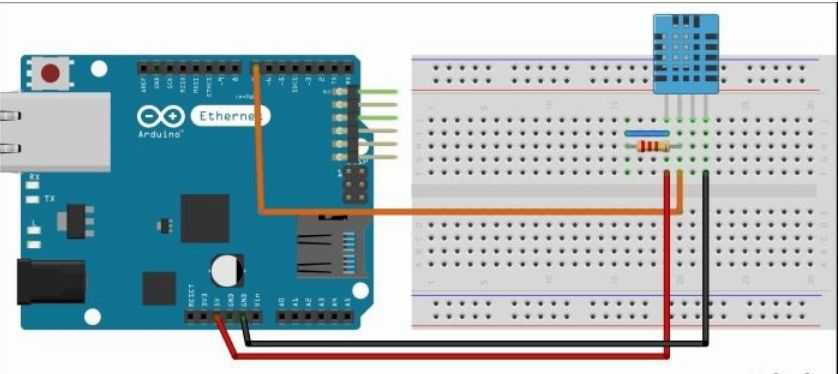
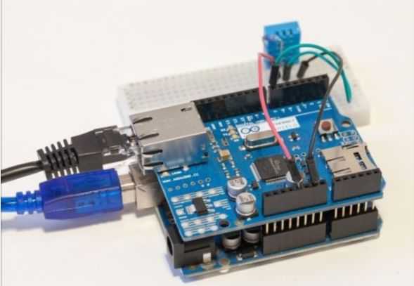
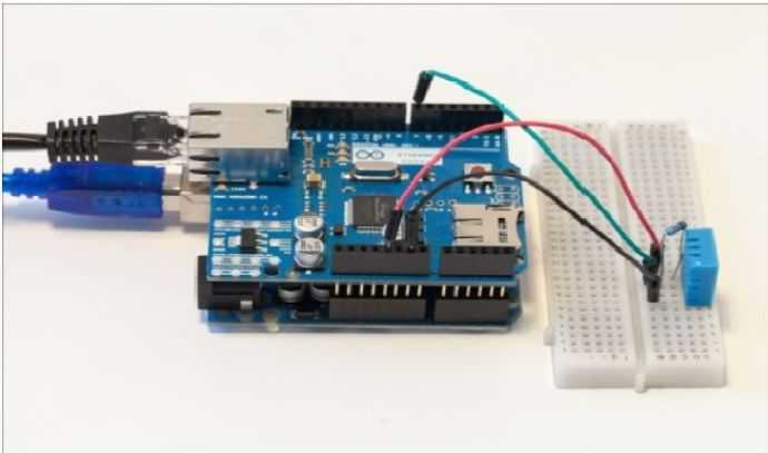
Let’s work with the hardware, we will need the following components for this part of our projectDHT11 temperature and humidity sensor / LM35 Temp sensor 4.7 ohm resistor
Breadboard
Jumper wires
Arduino UNO board
For the software components you will need the following Download and include the DHT11 Library form this link
https://playground.arduino.cc/Main/DHT11Lib
Download the ploting Library, from this link
http://www.flotcharts.org/
Download the database management system , we will use SQLite DMBS
http://www.sqlite.org/
For the web server we will use apache
If you are using of one these operating systems Windows: http://www.wampserver.com/en/
Linux: https://help.ubuntu.com/community/ApacheMySQLPHP Mac: https://www.mamp.info/en/
Steps
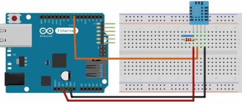
Plug the DHT11 sensor to the breadboard. Then, connect pin number 1 and pin number 2 of the sensor using the 4.7k ohm resistor
For the power supply. Connect pin number 1 of the sensor to Arduino 5v, and pin number 4 to Arduino GND. Now you can connect the pin number 2 of the DHT sensor to Arduino pin number 7
 It is now the time to send the data to the server
 Let’s build our first application using the Arduino Ethernet shield. But first, we need the IP address of your computer inside the Arduino sketch; also we will determine where the Arduino Ethernet shield should send the data
You can find the ip address of your computer, if you are using widows you can find the information you need under the network setting in control panel
In Linux / Mac operating system, just start the command line and type the following command: ifconifg and click enter
Now you are ready to build the Arduino sketch. First we will include the required libraries:
#include <SPI.h>
#include <Ethernet.h>
#include "DHT.h”
// now define the DHT11 pin on the Arduino as well as the type of the sensor
#define DHTPIN 7
#define DHTTYPE DHT11
//now let’s define the IP address
IPAddress server (192, 168, 1, 10);
// create an instance of the Ethernet client
EthernetClient client;
// and an instance of the DHT library
DHT dht(DHTPIN, DHTTYPE);
Serial.begin(115200)
If (Ethernet.begin(mac) == 0)
{
Serial.println(“Failed to configure the Ethernet shield”); Ethernet.begin(ip, mac);
}
Serial.pirnt(“IP Address: ”);
Serial.println(Ethernet.localIP());
float h = dht.readHumidity();
float t = dht.readTemperature();
/* now use this code to convert these measurements to strings*/ String temp = String((int) t); // this process called casting
/* for debugging purposes, we will write the following code to print these values on the serial port , also we will check if these values are correct or not */
Serial.print(“Temperature:” +temp);
Serial.pirnt(“Humidity:” + hum);
/* next thing we will do is, sending the data to the server, don’t panic if you cannot understand the following code, I will explain it later*/
If (client.connect(server, 80)){
If (client.connected()) {
Serial.println(“connected”);}
/* if this run successfully, we can make the request now. As in the previous part, but in this part we will use the GET request you can search for the difference between the GET and the POST request, so now enter the ip of your computer using this code */
Client.println(“GET/datalogger/datalogger.php?temp=” + temp)+ “&hum=” +hum +”HTTP/1.1”);client.println(“Host: 192.168.1.100”);
client.println(“Connection: close”);
client.println();
// then write the next code to read data from the server while (client.available()) {
while(client.available()){
char c = client.read();
Serial.print(c) ;
}
If (!client.connected()){
Serial.println();
Serial.println(“disconnecting”);
Client.stop(); delay(1000); // 1 second}
This is the whole code for this part // Include libraries
#include <SPI.h>
#include <Ethernet.h>
#include "DHT.h"
// DHT11 sensor pins #define DHTPIN 7
#define DHTTYPE DHT11
// IP address of your computer
IPAddress server(192,168,1,100); // Initialize the Ethernet client, an instance of the Ethernet client EthernetClient client;
// DHT instanceDHT dht(DHTPIN, DHTTYPE);
void setup() {
// Open serial communications Serial.begin(115200);
// Start the Ethernet connection
if (Ethernet.begin(mac) == 0) {
Serial.println("Failed to configure Ethernet using DHCP");
Ethernet.begin(mac, ip);
}
// Display IP
Serial.print("IP address: "); Serial.println(Ethernet.localIP());
// Give the Ethernet shield a second to initialize delay(1000);
Serial.println("Connecting...");
void loop() {
// Measure the humidity & temperature float h = dht.readHumidity();
float t = dht.readTemperature();
// Transform to String
String temp = String((int) t); String hum = String((int) h);
// Print on Serial monitor
Serial.println("Temperature: " + temp); Serial.println("Humidity: " + hum);
if (client.connect(server, 80)) { if (client.connected()) {
Serial.println("connected");
// Make a HTTP request:
client.println("GET /datalogger/datalogger.php?temp=" + temp + "&hum=" + hum + " HTTP/1.1");
client.println("Host: 192.168.1.100");
client.println("Connection: close");
client.println();
}
else {
// If you didn't get a connection to the server
Serial.println("connection failed");
}
// Read the answer
while (client.connected()) { while (client.available()) {
char c = client.read();
Serial.print(c);
}
}
// If the server's disconnected, stop the client: if (!client.connected()) {
Serial.println();
Serial.println("disconnecting."); client.stop();
}
// Repeat every second delay(1000);
}
In this part we will log the data in the data base
We are going now to use PHP to build the server of our project. If you are beginner in PHP, so you can check the following resource to learn the basics
http://php.net/manual/en/tutorial.phpwFirst we will see the content of the datalogger.php file. This file will deal the incoming requests from the Arduino board, then log the data in the database, and answer using a simple message. Note that this file has to be in a folder with the name (datalogger) on the web server.
Let’s write the code
$temperature = intval($_GET{“temp”});
$humidity = intval($_GET[“hum”]);
We will instantiate the connection with the database $db = new SQLite3(‘database.db’);
If you are not familiar with the SQL commands, just go to this websitehttps://www.w3schools.com/SQL/deFault.asp
Now let’s create the database columns : a unique ID that will be generated by SQLite, the timestamp column to know when the measurement was made, and the temperature and humidity data. This is done using the following code
$db->exec('CREATE TABLE IF NOT EXISTS measurements (id INTEGER PRIMARY KEY,
timestamp TIMESTAMP DEFAULT CURRENT_TIMESTAMP NOT NULL, temperature
INTEGER, humidity INTEGER);');
/*now we can insert the data as a new row in the database. Since SQLite will add the ID and timestamp, but we will add the temperature and the humidity */
$db->exec("INSERT INTO measurements (temperature, humidity) VALUES('$temperature', '$humidity');");
/* to check that the data was recorded correctly, you can simply create a file readout.php* which will read the data from the database /
$db = new SQLite3(‘ database.db’);/*and now we will write the query to the database to get the data we want */
$results = $db->query('SELECT id, timestamp, temperature, humidity FROM
measurements');
while($row = $results->fetchArray())
{$dataset[] = array(strtotime($row['timestamp']) *
1000,$row['temperature']);}
Echo json_encode($dataset);
/* If you want to learn more about JSON Visit http://json.org/
*/
/* we are going now to use the data in our database and display it on a graph, for this task we will use a JavaScript library called flot, which already included in our code, this library provides nice functions to plot the data on web pages, also it can plot the data in real time */
/* everything will happen insde an HTML file called plot.html. we will see the most important pieces oft the code here*/<script src="flot/jquery.js"></script>
<script src="flot/jquery.flot.js"></script>
<script src="flot/jquery.flot.time.js"></script>
<div id="placeholder" style="width:800px; height:450px;"></div> /* if you want to learn more about the JavaScript
You can check out this link
https://javascript.info/
*/
because we hava the timestamps as the x-axis, so we need to determine that the data for this position is a specific time, and that we want to display in this format hours, minutes, and seconds:
var options = {
xaxis: {
mode: "time",
timeformat: "%H:%M:%S"
}
};
$.ajax({
url: "readout.php",
type: "GET",
dataType: "json",
success: onDataReceived
})
function update() {
function onDataReceived(series) {
var data = [];
data.push(series);
$.plot("#placeholder", data, options);
}
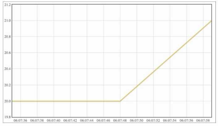 This is what you will see
 The whole code for this part
// web client code
// Include libraries #include <SPI.h>
#include <Ethernet.h> #include "DHT.h"
// DHT11 sensor pins #define DHTPIN 7
#define DHTTYPE DHT11
// IP address of your computer IPAddress server(192,168,1,100);
// Initialize the Ethernet client
EthernetClient client;
// DHT instance
DHT dht(DHTPIN, DHTTYPE);
// Open serial communications Serial.begin(115200);
// Start the Ethernet connection
if (Ethernet.begin(mac) == 0) {
Serial.println("Failed to configure Ethernet using DHCP");
Ethernet.begin(mac, ip);
}
// Display IP
Serial.print("IP address: "); Serial.println(Ethernet.localIP());
// Give the Ethernet shield a second to initialize delay(1000);
Serial.println("Connecting...");
} void loop() {
// Measure the humidity & temperature float h = dht.readHumidity();
float t = dht.readTemperature();
// Transform to String
String temp = String((int) t); String hum = String((int) h);
// Print on Serial monitor
Serial.println("Temperature: " + temp); Serial.println("Humidity: " + hum);
if (client.connect(server, 80)) { if (client.connected()) {
Serial.println("connected");
// Make a HTTP request: client.println("GET /datalogger/datalogger.php?temp=" + temp
+ "&hum=" + hum + " HTTP/1.1");
client.println("Host: 192.168.1.100");
client.println("Connection: close");
client.println();
}
else {
// If you didn't get a connection to the server
Serial.println("connection failed");
}
// Read the answer
while (client.connected()) { while (client.available()) {
char c = client.read();
Serial.print(c);
}
}
// If the server's disconnected, stop the client: if (!client.connected()) {
Serial.println();
Serial.println("disconnecting.");
client.stop(); }
// Repeat every second
delay(1000);
}
// this is the PHP code
error_reporting(E_ALL);
ini_set("display_errors", 1);
// Check that data is present
if (isset($_GET["temp"]) && isset($_GET["hum"])) { // Get data
$temperature = intval($_GET["temp"]);
$humidity = intval($_GET["hum"]);
// Create DB instance
$db = new SQLite3('database.db');
// Create new table if needed
$db->exec('CREATE TABLE IF NOT EXISTS measurements (id INTEGER PRIMARY KEY, timestamp TIMESTAMP DEFAULT CURRENT_TIMESTAMP NOT NULL, temperature INTEGER, humidity INTEGER);');
// Store data in DBif($db->exec("INSERT INTO measurements (temperature, humidity) VALUES ('$temperature', '$humidity');")){
echo "Data received";
}
else { echo "Failed to log data"; }}?>
//this is the plot code
<!doctype html>
<html lang="en">
<head>
<meta charset="utf-8">
<title>Temperature readout</title>
<script language="javascript" type="text/javascript" src="flot/jquery.flot.js"></script>
<script language="javascript" type="text/javascript" src="flot/jquery.flot.time.js"></script>
</head> <body>
<div id="placeholder" style="width:800px; height:450px;"></div>
<script> $(function () {
var options = {
xaxis: {
mode: "time",
timeformat: "%H:%M:%S"
}
};
// Update plot
function update() {
// Get data
$.ajax({
url: "readout.php",
type: "GET",
dataType: "json",
success: onDataReceived
});
// Plot data
function onDataReceived(series) { var data = [];
data.push(series);
$.plot("#placeholder", data, options);
}
// Time interval between updates setTimeout(update, 10);
}
// Update the plot
update();
});
</script>
//this is the read out script code <?php
// Show errors
error_reporting(E_ALL);
ini_set("display_errors", 1);
// Open database
$db = new SQLite3('database.db');
// Set default timezone
date_default_timezone_set('America/Los_Angeles'); // Get data
// Parse data
while($row = $results->fetchArray())
{
}
// Return data
echo json_encode($dataset);?>
// the data logger code
?php
error_reporting(E_ALL);
ini_set("display_errors", 1);
// Check that data is present
if (isset($_GET["temp"]) && isset($_GET["hum"])) {
// Get data
$temperature = intval($_GET["temp"]);
$humidity = intval($_GET["hum"]);
// Create DB instance
$db = new SQLite3('database.db');
// Create new table if needed
$db->exec('CREATE TABLE IF NOT EXISTS measurements (id INTEGER PRIMARY KEY, timestamp TIMESTAMP DEFAULT CURRENT_TIMESTAMP NOT NULL, temperature INTEGER, humidity INTEGER);');
// Store data in DBif($db->exec("INSERT INTO measurements (temperature, humidity) VALUES ('$temperature', '$humidity');")){
echo "Data received";
}
else {
}
}
?>
In this part we are going to deal with the SD cards to store the data, it also should be in FAT32 format
This is the parts you will need in our final part The Arduino UNO
The Arduino Ethernet shield
The DHT11 sensor
A MicroSD card
A breadboard
Jumper wires
now connect the Arduino and the SD card as shown
This is the whole code for this part
//datalogger code
// Include libraries
#include "DHT.h"
#include <SD.h>
#include <Time.h>
#include <Ethernet.h> #include <EthernetUdp.h> #include <SPI.h>
// DHT11 sensor pins #define DHTPIN 7
#define DHTTYPE DHT11
// Chip select pin
const int chipSelect = 4;
// NTP Server
IPAddress timeServer(132, 163, 4, 101); const int timeZone = 1;
// Create UDP server EthernetUDP Udp;
unsigned int localPort = 8888;
DHT dht(DHTPIN, DHTTYPE);
void setup() {
// Open serial communications Serial.begin(9600);
// Start Ethernet
if (Ethernet.begin(mac) == 0) {
// no point in carrying on, so do nothing forevermore:
while (1) {
Serial.println("Failed to configure Ethernet using DHCP"); delay(10000);
}
}
// Init SD card
Serial.print("Initializing SD card..."); pinMode(10, OUTPUT);
if (!SD.begin(chipSelect)) {
Serial.println("Card failed, or not present"); // don't do anything more:
return;
Serial.println("card initialized.");
// Initialize DHT sensor dht.begin();
// Print server info
Serial.print("IP number assigned by DHCP is "); Serial.println(Ethernet.localIP());
Udp.begin(localPort);
Serial.println("waiting for sync");
setSyncProvider(getNtpTime);
void loop() {
// Measure the humidity & temperature float h = dht.readHumidity(); float t = dht.readTemperature();
// Transform to String
String temp = String((int) t); String hum = String((int) h);
// Format time
String log_time = String(day()) + "/" + String(month()) + "/" + String(year()) + " " + String(hour()) + ":" + String(minute()) + ":" + String(second());
// Open file
File dataFile = SD.open("datalog.txt", FILE_WRITE);
// Write data to file
if (dataFile) {
dataFile.println(dataString);
dataFile.close();
Serial.println(dataString);
}
else {
Serial.println("error opening datalog.txt"); }
}
const int NTP_PACKET_SIZE = 48; // NTP time is in the first 48 bytes of message
byte packetBuffer[NTP_PACKET_SIZE]; //buffer to hold incoming & outgoing packets
time_t getNtpTime() {
while (Udp.parsePacket() > 0) ; // discard any previously received packets
Serial.println("Transmit NTP Request");
sendNTPpacket(timeServer);
uint32_t beginWait = millis();
while (millis() - beginWait < 1500) {
int size = Udp.parsePacket();
if (size >= NTP_PACKET_SIZE) {
Serial.println("Receive NTP Response");
unsigned long secsSince1900;
// convert four bytes starting at location 40 to a long integer secsSince1900 = (unsigned long)packetBuffer[40] << 24; secsSince1900 |= (unsigned long)packetBuffer[41] << 16; secsSince1900 |= (unsigned long)packetBuffer[42] << 8; secsSince1900 |= (unsigned long)packetBuffer[43];
}
}
Serial.println("No NTP Response :-(");
return 0; // return 0 if unable to get the time
// send an NTP request to the time server at the given address void sendNTPpacket(IPAddress &address)
{
// set all bytes in the buffer to 0
memset(packetBuffer, 0, NTP_PACKET_SIZE); // Initialize values needed to form NTP request // (see URL above for details on the packets) packetBuffer[0] = 0b11100011; // LI, Version, Mode packetBuffer[1] = 0;
packetBuffer[2] = 6;
// Stratum, or type of clock // Polling Interval
packetBuffer[3] = 0xEC; // Peer Clock Precision
// 8 bytes of zero for Root Delay & Root Dispersion packetBuffer[12] = 49;
packetBuffer[13] = 0x4E;
packetBuffer[14] = 49;
packetBuffer[15] = 52;
// all NTP fields have been given values, now
// you can send a packet requesting a timestamp:
Udp.beginPacket(address, 123); //NTP requests are to port 123 Udp.write(packetBuffer, NTP_PACKET_SIZE);
Udp.endPacket();
// the read out.php code <?php
error_reporting(E_ALL); ini_set("display_errors", 1); $db = new SQLite3('database.db');
while($row = $results->fetchArray())
{
$dataset[] = array(strtotime($row['timestamp']) * 1000,$row['temperature']);
}
echo json_encode($dataset);
?>
// the plot.html code
<!doctype html>
<html lang="en">
<head>
<meta charset="utf-8">
<title>Temperature readout</title>
<script language="javascript" type="text/javascript" src="flot/jquery.flot.js"></script>
<script language="javascript" type="text/javascript" src="flot/jquery.flot.time.js"></script>
</head> <body>
<div id="placeholder" style="width:800px; height:450px;"></div>
<script>
$(function () {
var options = {
xaxis: {
mode: "time",
timeformat: "%H:%M:%S"
}
};
// Update plot
function update() {
// Store data
$.ajax({
url: "datalogger.php", type: "GET",
});
// Get data
$.ajax({
url: "readout.php", type: "GET",
dataType: "json",
success: onDataReceived
});
// Plot data
function onDataReceived(series) { var data = [];
data.push(series);
$.plot("#placeholder", data, options);
}
// Time interval between updates
setTimeout(update, 10);
}
// Update the plot
update();
});
</script>
// the datalogger.php code <?php
error_reporting(E_ALL);
ini_set("display_errors", 1);
// Arduino board
$url = 'http://192.168.1.103';
// Get cURL resource
$curl = curl_init();
// Set some options - we are passing in a useragent too here curl_setopt_array($curl, array(
CURLOPT_RETURNTRANSFER => 1,
CURLOPT_URL => $url,
));
// Send the request & save response to $resp
$resp = curl_exec($curl);
// Close request to clear up some resources
curl_close($curl);
// Get data
$json = json_decode($resp, true);
$temperature = intval($json["temperature"]);
$humidity = intval($json["humidity"]);
// Create DB instance
$db = new SQLite3('database.db');
// Create new table if needed
$db->exec('CREATE TABLE IF NOT EXISTS measurements (id INTEGER PRIMARY KEY, timestamp TIMESTAMP DEFAULT CURRENT_TIMESTAMP NOT NULL, temperature INTEGER, humidity INTEGER);');
// Store data in DB$db->exec("INSERT INTO measurements (temperature, humidity) VALUES ('$temperature', '$humidity');");
// Answer
echo "Data received"; ?>


