Chapter 10 -
More Hardware Projects
The similarity of the Xbox to the PC architecture allows hackers to borrow technology and expertise from the PC world when building hardware projects. As a result, PC hardware, monitors, cables, and peripherals have all been adapted to work with the Xbox. This chapter introduces some of these hardware projects, discovered, documented and implemented by hackers around the world.
The LPC Interface
Version 1.0 of the LPC (Low Pin Count) interface was defined by Intel in 1997. The LPC interface is a royalty-free bus that is designed to enable systems without explicit ISA or X-bus (ISA-like expansion bus for memory or generic I/O devices) capabilities. The need for the LPC interface stems from the large number of low bit-rate, high pin count devices and busses with incompatible interfaces found in a standard PC, such as the floppy disk, keyboard, mouse, serial, IrDA, parallel, ISA, and boot ROM interfaces. The aggregate bandwidth consumed by all these devices is small, but the number of signals required to support all of them easily exceeds the signal count required by higher-bandwidth buses such as the PCI or AGP bus. Making matters worse, not all configurations of computers requires all of these legacy I/O devices, and wasted pins and functions just eat away at profits. The cost of a pin on a chip package is high relative to the cost of the silicon required to support these simple interfaces. (A rule of thumb is that one package pin costs a penny, while in 0.13µ silicon, about ten thousand gates — enough logic to implement a small processor—costs a penny in silicon area, assuming the design is not bond-pad limited1.)
The LPC interface counters this problem with a single, low-pin count (seven required pins, versus the 36 pins required for an ISA bus) bus that operates at a high speed. All of the legacy I/O and expansion functions are mapped into this high-bandwidth bus, enabling system designers to create so-called “Super I/O” chips that in turn enable Southbridge chips with a much lower pin count. In addition, segregating functions between Super I/O chips and Southbridge chips allows designers to choose Super I/O and Southbridge chip combinations that provide the optimal set of features for a given application.
The LPC physical interface is quite simple. The interface is a 4-bit bi-directional bus that runs at a 33 MHz clock rate. The interface also has two “sideband” signals: one framing signal that indicates the start and end of LPC bus cycles, and one reset signal that forces al LPC peripheral devices into a known state for initialization purposes. In addition, there are a couple of optional signals for the LPC interface that provide DMA and interrupt capabilities as wel as power management for more sophisticated I/O devices. (More information on the LPC bus and its protocol can be found in the Intel Low Pin Count (LPC) Interface Specification, version 1.1. The specification can be found on the Intel corporate website at http://www.intel.com/design/chipsets/industry/lpc.htm.)
LPC Interface on the Xbox
The Xbox incorporates an LPC interface on the motherboard. The LPC interface in this case is used to implement a debug and test bus. One can connect a keyboard and mouse through this LPC interface, as well as an alternate boot ROM for diagnostic purposes. The LPC interface is activated to load alternate boot code when the FLASH ROM on the Xbox is not available. The lack of a FLASH ROM device can be simulated by forcing the lowest data bit (D0) of the FLASH ROM data bus to a level of zero volts.
Many speculate that the LPC interface is an essential part of the Xbox production line because of the alternate boot ROM ability provided by the LPC interface. Fully assembled Xboxes can be configured with a comprehensive self-test program via the LPC interface. Applying the CPU as a fast test controller allows defective units to be quickly and efficiently isolated on the factory floor without the cost of expensive testing machines.
For hackers, the alternate boot ROM facility provided by the LPC interface is an ideal mechanism for getting code into the Xbox. Valid LPC-loadable boot ROM images for the Xbox can be created by anyone since the cryptographically secured boot procedure of the Xbox is now fully understood. In fact, some vendors of alternate boot ROM devices for the Xbox have leveraged the regularity of the LPC interface’s pinout geometry on the Xbox motherboard to create ROM devices that instal without any soldering. These devices use a set of spring-loaded “pogo-pins,” similar to those used during production for Xbox testing, to contact the LPC interface with just a pressure-fit. (The pinout of the LPC bus as implemented on the Xbox can be found in Appendix F, “Xbox Hardware Reference.”)
Using the LPC Interface
The fact that the LPC interface is an industry standard is quite convenient for Xbox hardware hackers. First, there is a plethora of LPC-compatible interface devices, ranging from Super-I/O chips to firmware ROMs with built-in LPC interfaces. Second, the wide acceptance of the LPC interface as a diagnostic and convenience bus for generic PCs helps mitigate the legal risk of using the LPC interface and selling LPC interface devices. A firmware ROM for the LPC interface can be sold without any Xbox-specific contents since end-users can easily reprogram their LPC bus devices using a simple, cheap adapter for their PC. A further help to the legality of LPC firmware devices is that the Xbox’s LPC connector pinout is nearly identical to the one recommended by Intel for generic PCs. As a result, an LPC firmware device sold for the Xbox is very similar to an LPC firmware device sold for the standard PC.
One of the first LPC boot ROM devices was developed by Andy Green. The project is called “Cheapmod” and it is an SST 49LF020 device (256 kByte FLASH ROM with an integrated LPC interface) in a socket wired to an LPC-compatible header. According to Andy’s Cheapmod webpage, “http://warmcat.com/milksop/cheapmod.html,” “If you can get ahold of the $2.50 SST 49LF020, you can build an alternative BIOS for $4.” This device can be programmed using his “CheapLPC” programmer (http://warmcat.com/milksop/cheapLPC.html), a delightfully simple PC parallel-port based device that can (slowly) talk to and reprogram an LPC device. Many commercially available alternate firmware devices have been based off of or inspired by his design, including the Xodus/Matrix design. The Xodus/Matrix is a particularly interesting variant of Andy’s original design, as it was the first Xbox alternate firmware device to implement an entirely solderless installation procedure. This opened up the world of Xbox hacking to software-oriented hackers who were not inclined to solder wires into their Xboxes. (A photograph of the Xodus/Matrix can be seen in Figure 10-1.) The Xodus/Matrix device comes without any code programmed in it; the user must provide the alternate firmware image.
There are some important functional considerations when selecting a FLASH ROM chip with an LPC interface for use with the Xbox. The most significant is that the native Xbox architecture allocates a 16 MB area for the boot ROM. If the physical boot ROM is smaller than 16 MB in size, the boot ROM contents are aliased to fill up the entire 16 MB space. This gives Xbox designers more flexibility in choosing the size of the ROM chip without causing problems with routines that uses both bottom- and top-relative addressing.
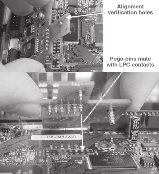
Figure 10-1: The solderless Xodus/Matrix alternate firmware device, showing the spring-loaded “pogo-pin” contacts that enable a solderless connection to the LPC connector on the Xbox motherboard.
Let’s make the concept of bottom- and top-relative addressing more concrete with an example. The addresses for the 16 MB boot ROM area in the Xbox spans from 0xFF00.0000 to 0xFFFF.FFFF. Programs on the Xbox that use bottom-relative addressing will compute addresses using 0xFF00.0000 + offset (bottom address plus offset), while programs that use top-relative addressing will use 0xFFFF.FFFF – offset (top address minus offset). Suppose a 1 MB boot ROM is installed in the Xbox. This means that the processor will see 16 identical copies of this 1 MB ROM spread evenly over the 16 MB ROM address space. In other words, the contents of the boot memory appear identical for every address A + 0xFF00.0000 + n * 0x0010.0000, n = 0 through 15, A = 0 through 0x000F.FFFF. As a result, programmers can pack data into the smaller 1 MB boot ROM using both top- and bottom-relative addressing without having to change any of their code: A valid copy of the ROM image appears near both the top- and the bottom-relative base addresses. Now, suppose that Microsoft decided to save on cost and shrink their 1 MB boot ROM down to a 256 kB boot ROM. The processor now sees 64 identical copies of this 256 kB boot ROM distributed over the 16 MB ROM address space, and all of the old code that uses bottom- and top-relative addressing still works. Significantly, the CPU in the Xbox is hard-wired to start executing code on power-up from an address located 16 bytes from the top of memory (its “reset vector”), while the hardware initialization routines wired into the Xbox chipsets use ROM locations located near the bottom of the 16 MB FLASH ROM space. As a result, the Xbox hardware requires an LPC ROM implementation that is either 16 MB in size, or else aliases a smaller ROM’s contents throughout the FLASH ROM address space. (The SST 49LF020 is one of the few LPC FLASH ROMs that aliases the ROM’s contents over the whole address space. Arguably, this feature is actually a bug: By ignoring the upper address bits and aliasing the ROM’s contents over the whole address space, this chip occupies space that could be allocated to other functions. As a result, SST has released an updated “A-step” of the part, called the 49LF020A, that does not alias the ROM’s contents over memory. Likewise, the A-step silicon will not work as an alternate firmware device for the Xbox.)
Alternate Firmware Devices vs. Modchips
An alternate firmware device is a hardware module that provides a method for running user-specified firmware on the Xbox hardware. Alternate firmware devices are distinguished from the so-called “modchip” in that an alternate firmware device is furnished as a blank device and has no inherent ability to circumvent copyright control mechanisms. A blank LPC-interface ROM device, for example, is an alternate firmware device: you could burn a copy of the U.S. Bill of Rights on it if you wanted. Any user-installed FLASH ROM that comes blank is also an alternate firmware device. A modchip, on the other hand, colloquially implies a device that is crafted for playing game backups and otherwise modifying or removing DRM (digital rights management) policy restrictions. Hence, the term modchip encompasses certain boot ROM devices that have been programmed with code that enables DRM policy modifications, as well as devices such as “patchers” that contain no ROM and operate by dynamically patching a few key Xbox firmware locations as the firmware is loaded for execution.
The Other 64 MB of SDRAM
An astute observer will note that there are two missing chips on the top side of the Xbox motherboard, and that these missing chip spots look suspiciously like the spots currently occupied by memory chips. Flip the board over, and there are two more unoccupied chip footprints. These empty footprints are in fact for memory chips. The location of these blank spots is shown in Figure 10-2.
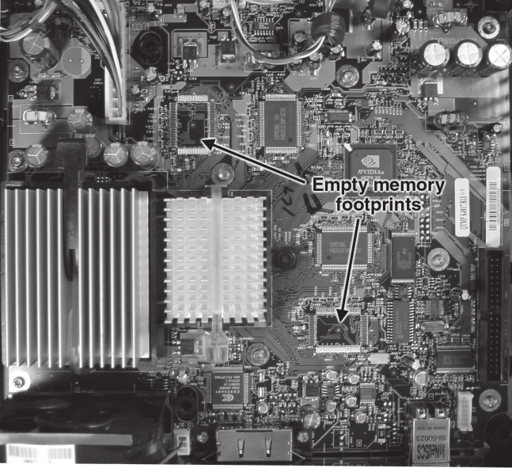
Figure 10-2: The unpopulated memory footprints on the Xbox motherboard.
Fiduciaries
Look at an unpopulated memory spot on the Xbox motherboard. The silver dot surrounded by a dark annulus inside these unpopulated chip footprints is called a fiduciary. Fiduciary patterns are used by circuit board assembly machines as reference points for aligning large chips with many pins. They are designed to be easily recognized by the machine vision systems employed in board assembly machines. Specially shaped fiduciaries can also be used to enable automatic identification of the orientation and type of a circuit board.
The next logical question is, of course, “Can you double the Xbox’s memory size to 128 MB by soldering suitable memory chips into the open slots on the Xbox motherboard?” The answer is in fact yes, but the initialization code for the Xbox needs to be modified in order for the chipset to recognize and use the extra memory. In addition, the extra memory does not help graphics or gaming performance. Xbox games are not designed to take advantage of the extra memory, so the extra memory will typically sit around unused. The extra memory spots are provided primarily for the manufacture of special consoles for game developers. Game developers can use the extra memory to ease the transition of games into the Xbox’s relatively tight memory footprint, as well as for keeping debug, performance monitoring, and test utilities resident in memory that are not part of the game image. Note that the extra memory could be leveraged by home-brew software, but the difficulty of obtaining and installing the memory chips makes Xbox memory expansions more of an interesting soldering practice exercise than a practical modification.
Xbox VGA
There is a little bit of confusion about what an Xbox VGA adapter does. Many Xbox VGA adapters are actually TV-to-VGA converters. In other words, they take the low resolution TV output from the Xbox and run it through a line doubler to yield a low-quality VGA display. A true Xbox VGA adapter actually configures the Xbox to output a much higher resolution video output, yielding a better-than-TV quality display on a VGA monitor.
The VGA adapter configures the Xbox graphics mode using designated pins in the AVIP (Audio Video I/O Port) connector. The main problem with this approach is that a game has to be specially written to support this higher resolution mode. As a result, some games will not work with a true Xbox VGA adapter, but fortunately going back to TV resolution is as easy as plugging in the standard TV adapter cable.
The original Xbox-VGA adapter was developed by Ken Gasper. He sells a version of it on his website at http://xboxvga.xemulation.com. Currently, he offers the Xbox-VGA adapter in a “bare board” form as well as in a fully assembled form. If you are looking for an interesting hardware hacking project for the Xbox that is both useful and will hone your circuit assembly skills, it may be worth purchasing one of his bare boards and attempting to assemble the adapter yourself.
Appendix F contains a pin diagram of the Xbox AVIP.
Mass Storage Replacement
The Xbox contains a DVD-ROM drive and a hard drive, both of which use the PC standard IDE interface for talking to the Xbox motherboard. The DVD-ROM drive also has a proprietary power and DVD tray state connector. A popular and sometimes necessary hacking activity for the Xbox is replacing these drives.
Users replace or tweak the DVD-ROM because the native Xbox DVD-ROM drive is unable to read CD-Rs and many types of CD-RW media. This can be particularly annoying for those who are trying to install Xbox-Linux for the first time, or for users who are trying to rip music from their CD-R collection to the Xbox hard drive.
There are many methods for replacing and tweaking the Xbox DVD-ROM drive. Some Xbox DVD-ROM drive models can have their laser intensity adjusted to improve their ability to read CD-R and CD-RW media. This is a potentially risky operation, since you can permanently damage your DVD- ROM drive by improperly adjusting the power output of the laser, but many hackers have reported that a properly executed procedure results in better media compatibility. I suggest a web-search for the latest news and techniques since the style and model of DVD-ROM drive used in the Xbox varies frequently. In addition, the Xbox DVD-ROM drive can be replaced outright with a standard PC DVD-ROM. The problem with this method is twofold. First, a regular PC DVD-ROM drive cannot read original Xbox game disks due to physical security measures built into an Xbox game disk. Second, a PC DVD-ROM drive needs to be adapted to the custom DVD power and traystate connector on the Xbox motherboard.
The easiest, but ugliest,way is to install a standard PC DVD-ROM drive but leave the Xbox DVD-ROM drive connected through its proprietary cable. In this method, the gray IDE cable is connected to the standard PC DVD-ROM drive (set to slave mode through jumper configurations on the drive), and power is stolen from the hard drive’s power connector using a standard power splitter cable. The Xbox DVD-ROM drive remains in place, but with its IDE connector empty and with the proprietary yellow power-and-tray-state cable installed. The purpose of the Xbox DVD-ROM drive is to serve as a dummy drive that is used to manually relay the state of the DVD drive tray to the Xbox. In other words, the user needs to manually replicate the state of the standard PC DVD-ROM’s tray using the Xbox DVD-ROM’s tray during a media change event.
The exact procedure for operating an Xbox in this configuration varies depending upon the particular PC DVD-ROM drive model and the nuances of the Xbox hardware configuration, so again, I suggest a web-search for the latest information. There are also some websites that describe how to adapt select PC DVD-ROM drive models to work with the Xbox’s proprietary tray state and power connector. A project like this is a good intermediate-level one for hackers who are basical y comfortable with soldering and screwdrivers. The modifications performed on the standard DVD-ROM drive allow the state of the standard drive’s DVD tray to be accurately transmitted to the Xbox. They do not allow you to play original games, however, unless the Xbox has been modified with additional hardware that circumvents the security checks on the DVD ROM drive. Even without the ability to play games, this is still a useful technique for ferreting out Xbox-Linux installation problems and for enhancing the ability of the Xbox to rip your CD collection or to watch DVDs. (Note that returning the IDE connector back to the Xbox DVD-ROM drive will restore the original gaming functionality of the Xbox.)
Xbox hard drives also need replacing from time to time. Serious software developers for the Xbox find it advantageous to install a higher capacity hard drive in the Xbox, and users with broken hard drives also desire to replace their hard drives. Unfortunately, the OEM Xbox hard drive contains copyrighted Microsoft programs. Xbox hard drives are also protected with a firmware lockout, which makes installing a new hard drive with original gaming functionality rather challenging, especially in terms of legal issues. The firmware lockout is also unique to each hard drive, preventing you from replacing your hard drive with a used Xbox hard drive. However, if you only wish to run Xbox-Linux or other homebrew programs and do not care about playing games, installing a new hard drive in the Xbox is as easy and as legal as installing a hard drive in any PC.
1 The circuits on a chip are typically surrounded by squares of metal (“bond pads”) that are wired to the pins on the chip’s packaging. A chip is said to be bond-pad limited when the area required for the ring of bond pads exceeds the area required by the circuitry inside the chip. The cost of excess pins becomes even higher in the case that a chip is bond-pad limited.

